
Are VLAN and VxLAN still confusing you? This article will explain the difference.
01 What is VxLAN?
VxLAN, short for Visual eXtensible Local Area Network, is an extended protocol of VLAN, as indicated by its name.
VxLAN is essentially a tunneling encapsulation technology. It uses the TCP/IP protocol stack’s conventional approach—encapsulation/decapsulation technology—to encapsulate Ethernet frames at Layer 2 (L2) into UDP datagrams at Layer 4 (L4) and then transfers them over a Layer 3 (L3) network, making it appear as if the Ethernet frames are still within a broadcast domain, even though they are actually traversing an L3 network without being aware of its presence.
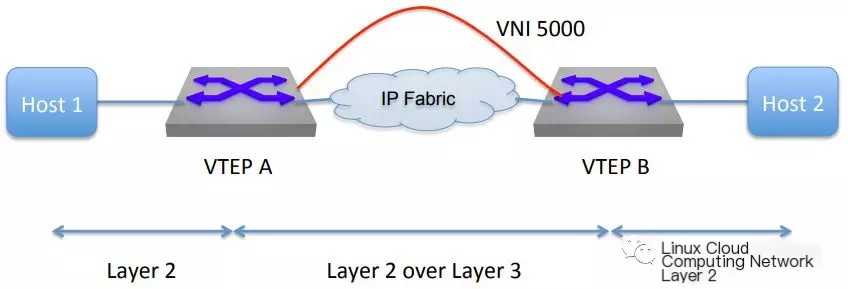
As shown in the diagram below, there are L2 broadcast domains on either side, with an L3 network in the middle. VTEP is the VxLAN Tunnel Endpoint. When the L2 Ethernet frame reaches the VTEP, it communicates across the L3 network via VxLAN encapsulation. This encapsulation “hides” the presence of the L3 network, making the entire process resemble transmission within the same L2 broadcast domain.
 >
>
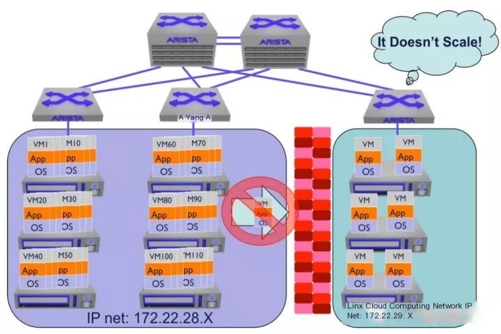
VxLAN was developed in response to the growing demand for network virtualization technology. As data center networks continued to expand, companies like Cisco, VMware, and Arista Networks realized that traditional VLAN isolation could no longer handle the massive growth of virtualized devices. As a result, they jointly drafted this protocol, which was finalized in 2014 and defined by RFC 7348.
02 Why is VxLAN needed?
There are three main reasons why network virtualization necessitates transitioning to VxLAN.
1. Limitations on the Number of VLAN IDs
As virtualization technology advanced, the network configuration shifted from individual physical devices to virtual devices.
In the past, a single physical device (whether a server or a network device) could support a few dozen ports, making VLAN usage more than sufficient. However, in a virtualized environment, the situation is vastly different, with a single physical host potentially virtualizing hundreds or thousands of virtual devices. An entire cloud data center might need to divide into thousands of broadcast domains, but VLANs are limited to a maximum of 4094, which is insufficient.
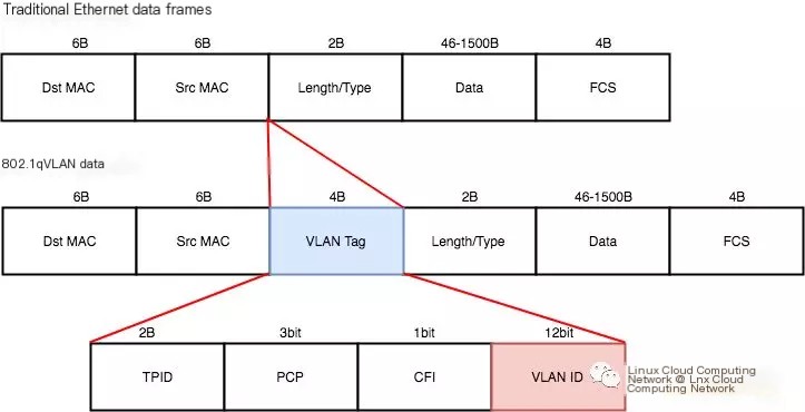
We can understand this limitation by analyzing the VLAN packet format. The 802.1Q standard defines the VLAN protocol Ethernet frame format as follows:
 >
>
You can see that the VLAN frame introduces the VLAN Tag field to the Ethernet frame, which consists of TPID, PCP, CFI, and VID parts. The VID represents the VLAN ID, occupying 12 bits with a range of 0 to 4095, where 0 and 4095 are reserved and not available for user use. Therefore, an Ethernet can be divided into a maximum of 4094 VLANs, which is the origin of the value 4094.
2. Better Utilization of Multiple Network Links
VLANs use STP to manage multiple network links to avoid loops during data transmission. STP selects one working link based on priorities and costs, and the remaining links serve as backup links, resulting in an active-passive mode. Although this avoids loops and enhances availability, it fails to fully utilize multiple links to improve performance. For users, it means paying N times the cost but enjoying only one-time service.
VxLAN, on the other hand, can transparently transmit L2 data over an L3 network, allowing it to use protocols like ECMP (Equal-cost multi-path) for multiple paths to work simultaneously, resulting in an active-active mode. This way, when network traffic becomes heavy, load balancing of traffic can be achieved, improving data transmission performance.
3. TOR Switch MAC Address Table Limitations
Switches operate by using MAC address tables to complete Layer 2 data forwarding. Before virtualization technology, a TOR (Top of Rack) switch would connect one physical host to a port and associate it with one MAC address. With the advent of virtualization technology, a single physical host could virtualize dozens or even hundreds of virtual machines. Although the TOR switch’s port still connects to a physical host, it corresponds to multiple MAC addresses, as shown in the diagram:
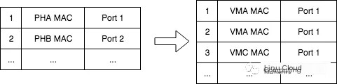
This inevitably leads to an expanded TOR MAC address table. The switch has limited space for its MAC table, and overflow would result in continual flooding, increasing processing burdens.
However, if VxLAN is used, VTEP encapsulates the virtual machine’s Layer 2 frames and transmits them over a Layer 3 network. Typically, a physical machine corresponds to one VTEP, and all virtual machines on that host share the VTEP. Therefore, the TOR switch’s MAC address table only needs to record one VTEP entry for each physical machine. This avoids the MAC address table explosion issue.
4. Flexible Deployment and Migration of Virtual Machines
- Deployment: To deploy a virtual machine on VLAN 100, it must be deployed on a physical machine supporting VLAN 100. As shown in the diagram, assume the left and right areas belong to VLAN 100 and VLAN 200. If VLAN 100 has many virtual machines deployed but VLAN 200 only a few, new virtual machines need to be deployed on the left side, increasing its burden.
- Migration: When migrating a virtual machine from the left area to the right, because they belong to different VLANs, the IP addresses differ, preventing direct migration, which can lead to an uneven load distribution across the cluster.
VxLAN resolves these problems through encapsulation, allowing data to traverse L2 limits and transmit over an L3 network. Virtual machines can be deployed and migrated without being restricted by physical network boundaries, maintaining balanced utilization across the data center.
03 VxLAN Packet Format
VxLAN is a type of tunneling encapsulation technology, meaning its packet format is also a type of encapsulated structure, as illustrated in the diagram below.
The innermost layer is the original L2 Ethernet frame, which is the data frame sent by the virtual machine. The VxLAN header is then encapsulated, putting the VxLAN frame inside a UDP segment on the physical network, followed by an IP header and a MAC header. To distinguish from the inner original Ethernet frame, the outer layer encapsulation adds an outer IP and outer MAC header.
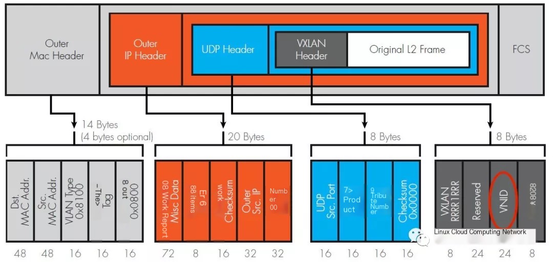
The VxLAN header consists of 8 Bytes with:
- Flags: Occupies 8 bits, specifically
RRRRIRRR, whereImust be set to 1 to indicate a valid VxLAN ID, and the other seven bitsRare reserved and set to 0. - VNI (VxLAN Network Identifier): Occupies 24 bits, specifying the VxLAN ID, which extends the ID count to
2^24 = 16777216, roughly 16 million. - Reserved: Consists of two fields, occupying 24 bits and 8 bits, both set to zero as reserved fields.
The default destination port for the UDP header is 4789, which is the port assigned by IANA for VxLAN protocol usage.
The other fields are typical TCP/IP protocol fields and will not be elaborated here.
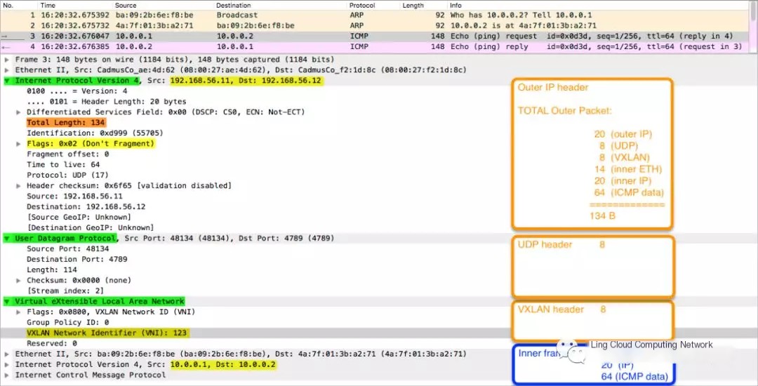
If the above diagram still seems abstract, the following Wireshark capture provides a more intuitive view:
04 VxLAN Data Transmission
Here’s a specific example illustrating the VxLAN network structure and data transmission.
The diagram below shows a VxLAN-based network structure:
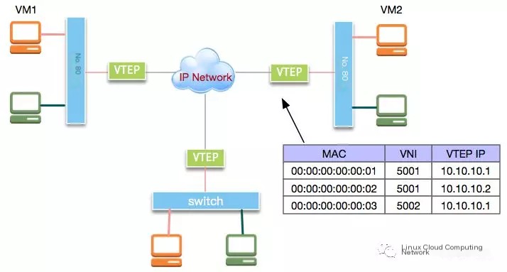
In the diagram, a VTEP (VxLAN Tunnel Endpoint) is a device within the VxLAN protocol that performs encapsulation and decapsulation of raw data packets. It can be implemented via hardware or software.
Suppose VM1 pings VM2; this is how the communication process occurs:
- VM1, unaware of VM2’s MAC address, sends out an ARP request.
- The VTEP on VM1’s host encapsulates the ARP request packet and broadcasts it to other VTEPs. Meanwhile, it records VM1’s entry in the MAC address table.
- VM2’s host VTEP receives the ARP request packet, decapsulates it, and forwards the original packet to VM2, simultaneously recording VM1’s MAC address entry.
- VM2 sends an ARP response, which gets encapsulated by the VTEP. Since VM1’s address is previously learned, it’s directly unicast to VM1’s host VTEP while recording VM2’s MAC entry.
- The VTEP on VM1’s host receives the ARP response packet, decapsulates it, and forwards it to VM1 while recording VM2’s MAC entry.
- With VM2’s MAC address, VM1 sends an ICMP packet. Since VM2’s address is learned, the VTEP directly encapsulates and unicasts it to VM2’s host.
- VM2’s host VTEP decapsulates and forwards the packet to VM2.
- VM2 constructs an ICMP response packet, sending it through the same process back to VM1, completing the ping operation.
05 Summary
While VxLAN offers many advantages over VLAN, it does not completely replace VLAN in the foreseeable future; it depends on the specific usage scenarios. VxLAN’s benefits are more apparent in large-scale environments, but when the network device scale consists of only a few hundred virtual or physical devices, VLAN is sufficient. Additionally, VxLAN’s encapsulation and decapsulation mechanism may impact performance, requiring a comprehensive assessment.
VxLAN finds extensive use in Linux, OVS, container networks, and more, with further elaboration reserved for future discussions.
Creating original content is not easy. If you find this article helpful, please give it a like or share it as support for this original work! Thank you!
References:
https://tools.ietf.org/html/rfc7348
http://www.just4coding.com/blog/2017/05/21/vxlan/
https://zhuanlan.zhihu.com/p/36165475
https://www.openstack.org/assets/presentation-media/OpenStackOverVxlan.pdf