
1. Introduction to Time To Live (TTL)
TTL, short for Time To Live, is known in Chinese as survival time, and it is a crucial parameter in the IP header. By examining the TTL value, we can assess the current operational status of the network’s IP layer.
TTL informs the routers on the network whether a data packet has existed in the network for too long and should be discarded. The original concept of TTL was to establish a time limit, beyond which the packet would be dropped. Since the TTL value is decreased by at least one by each router the packet passes through, TTL typically represents the maximum number of routers a packet can traverse before being discarded. When the TTL reaches zero, the router drops the packet and sends an ICMP message to the packet’s original sender.
There are numerous reasons why a data packet might not reach its destination within a certain timeframe. For instance, incorrect routing table configurations may cause packets to loop indefinitely. The solution to this issue is to discard the packet after a set period and send a message to the sender, who will then decide whether to resend the packet. When this network issue occurs, the packet continually gets sent to the erroneously configured router, with the TTL reducing by one each time, until TTL reaches zero, at which point the router discards the packet, leading to network transmission errors.
The default TTL value varies with different operating systems and transmission protocols. Table 1 lists the default TTL values for common operating systems when transmitting through TCP and UDP protocols.
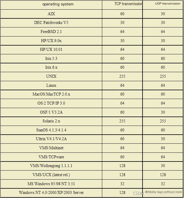
(Table 1: Default TTL Values for Different Operating Systems)
2. Viewing Packet TTL Values and Analyzing Transmission Failures
Network devices function based on internal operating systems (some hardware devices have systems pre-installed on chips). When network transmission failures occur, we can use network diagnostic software in conjunction with the information from the table above to inspect the packets traversing the network and check the TTL value to determine if the failure is due to erroneous routing or other causes. Figure 1 shows how to view a packet’s TTL value using the Colasoft Network Analyzer 5.0.
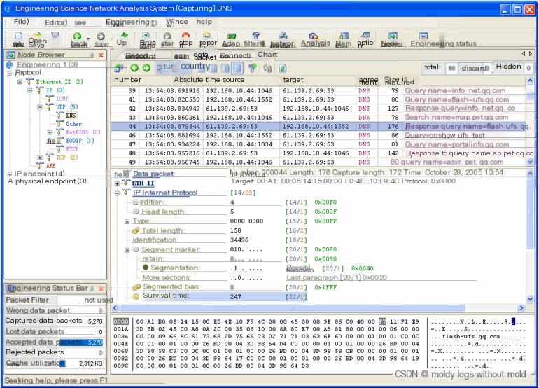
(Figure 1: TTL Value as Seen in Colasoft Network Analyzer)
In the figure, the survival time (TTL) is 247. Using Table 1, we determine that this packet has traveled through 255-247=8 routers from the source (here, 61.139.2.69) to the destination (here, 192.168.10.44), and no transmission failures occurred during the journey.
Note:
- To determine how many routers a packet has passed through on the network, subtract the captured packet’s TTL value from the source device’s default TTL value;
- If the source device’s default TTL is unknown, generally use the default value greater than and closest to the captured packet’s TTL;
- The TTL field is 1 byte long, with a maximum TTL value of 255;
By checking the TTL of packets, we can determine if network transmission is normal. If the TTL value of captured packets is too low, it indicates a high possibility of network transmission failure, necessitating prompt inspection of the routing table configurations on the network’s Layer 3 devices and the routing table information on each host.