

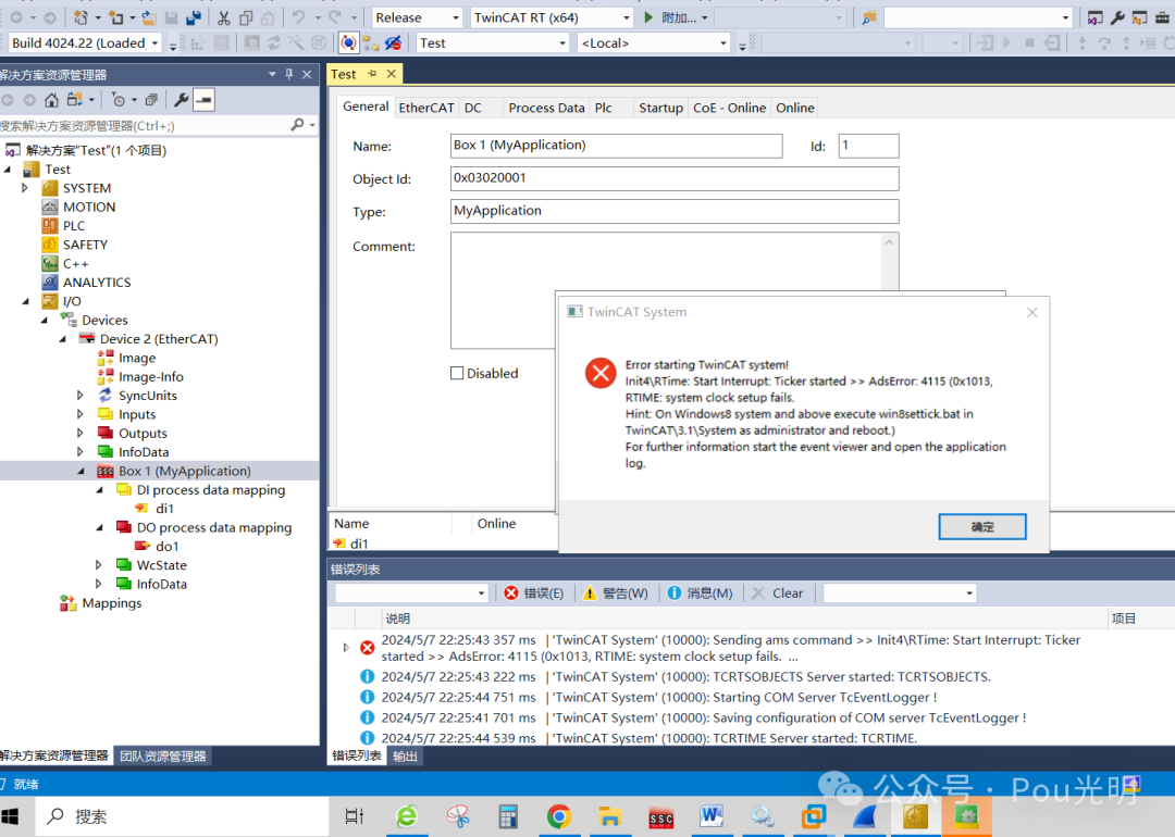
Save your work and perform a TwinCAT restart.
At this point, my device cannot enter the OP state, and WireShark has no data.

① After clicking the green button, click the confirm button in the popup to clear the popup, but still cannot enter the OP state.

② Reload the device.


Choose yes.
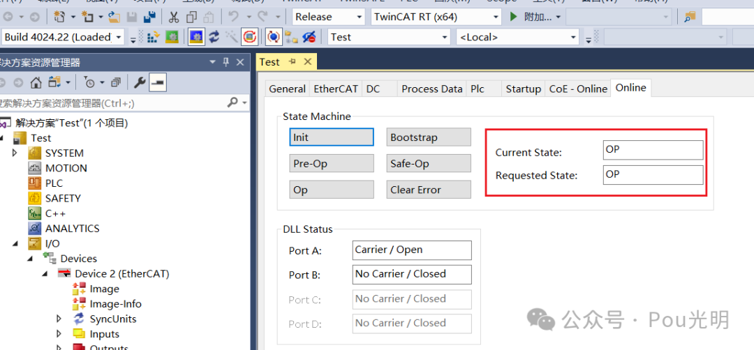
It’s fine now.
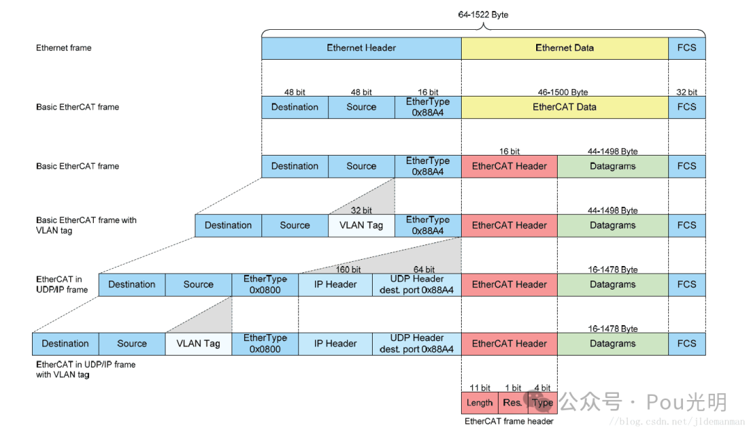
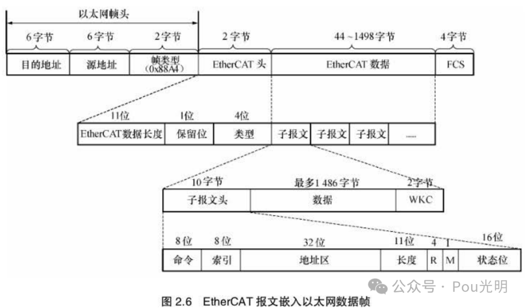
EtherCAT uses standard IEEE 802.3 Ethernet frames with a frame type of 0x88A4. An EtherCAT frame consists of an EtherCAT frame header and an EtherCAT message with a maximum payload length of 1498 bytes.
The EtherCAT communication frame structure adopts a standard Ethernet frame structure, formed by modifying the traditional protocol. EtherCAT data frames with a special frame type are inserted into the standard protocol. In other words, the data content of the standard protocol is the EtherCAT data frame. The special frame type is marked with 0x88A4. Thus, Ethernet CAT communication is completely compatible with standard Ethernet communication. The EtherCAT data frame structure is shown in the diagram.
Study with two comparisons.

The EtherCAT subframe mainly consists of three parts: the subframe header, the subframe data, and the working counter WKC (Working Counter). The purpose of the WKC is to determine whether the subframe has been read or inserted by the slave by recording the number of operations on the subframe by the slave.
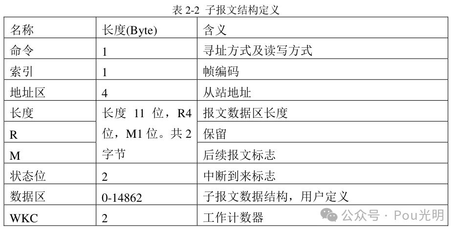
The structure definition of EtherCAT subframes is shown in Table 2-2. The subframe includes seven parts: command, index, address field length, flag bits, status bits, data field, and working counter. The command in the message is usually 8 bits and indicates the addressing method and read/write operations; the index is the frame code; the communication address of the slave is the 32-bit binary code in the address field; the flag bit M indicates follow-up frames, if the EtherCAT data frame has multiple subframes, flag bits of all but the last subframe need to be set; the subframe data is user-defined, and the length is usually 1486 bytes.
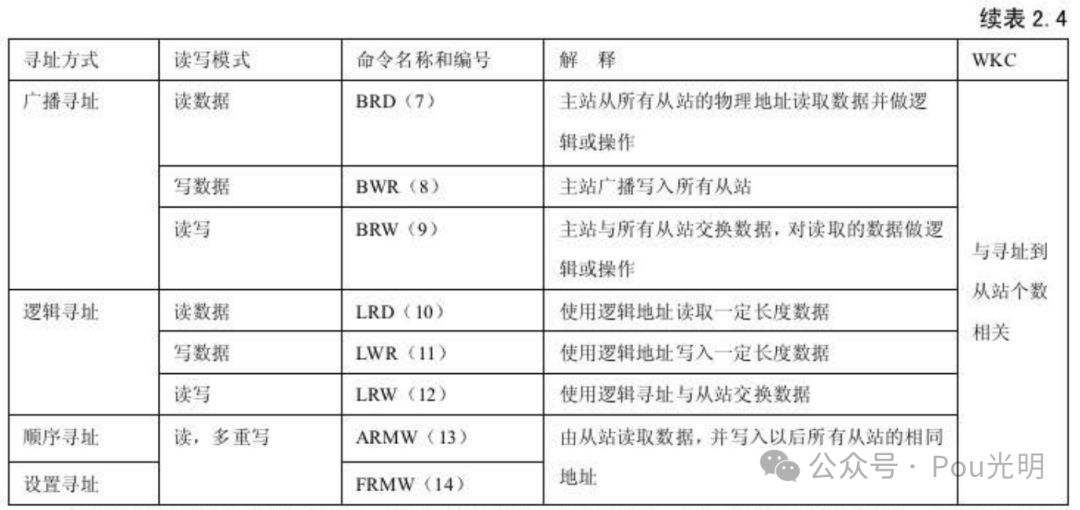
EtherCAT subframe services are all carried out as described from the master station. The data link specifies services for internal slave storage, reading, writing, and exchanging (read immediately then write) data. The read/write operations and addressing method jointly determine the type of subframe communication service, represented by the command byte in the subframe header. All commands supported by EtherCAT are listed in Table 2.4.

First prepare the above basic knowledge, message analysis is always monotonous and joyful, joyful from ignorance to a little understanding.
Look at the first captured frame data, 29 bytes.
6 bytes (010105010000) target mac;
6 bytes (000000000000) source mac;
0x88A4(88a4); …… Current total 14 bytes
EtherCAT frame header (16bit, 2 bytes)
…. .000 0000 1101 = Length: 0x00d …… 11 bits
…. 0… …. …. = Reserved: Valid (0x0) …… 1 bit
0001 …. …. …. = Type: EtherCAT command (0x1) …… 4 bits
EtherCAT datagram(s): ‘BWR’: Len: 1, Adp 0x0, Ado 0x101, Wc 0
EtherCAT datagram: Cmd: ‘BWR’ (8), Len: 1, Adp 0x0, Ado 0x101, Cnt 0
Header
Cmd: 8 (Broadcast Write)
Index: 0x80
With each subframe sent under the BWR command, the index increases by 1, ranging from 0x80 to 0xff.
Slave Addr: 0x0000
Offset Addr: 0x0101
For non-logical addressing commands, the address field will be split into Slave Addr and Offset Addr, that is, Slave Addr: 0x0000, Offset Addr: 0x0101, note this is little-endian mode, you’ll know how to read it; for logical addressing, the address field will have only one 32-bit Log Addr: 0x01010000. (I still don’t understand…)
Length: 1 (0x1) – No Roundtrip – Last Sub Command
…. .000 0000 0001 = Length: 1
..00 0… …. …. = Reserved: Valid (0)
.0.. …. …. …. = Round trip: Frame is not circulating
0… …. …. …. = Last indicator: Last EtherCAT datagram
Data field length of the message, little-endian mode, correctly sorted is 0x0001, which is expanded into binary:
0000 0000 0000 0001;
Replace unrelated bits with *:
0*** **** **** **** The highest bit is the M in the frame structure, 0 indicates only one frame, 1 indicates subsequent frames;
*000 0*** **** **** The high 2, 3, and 4 bits are reserved but practically, using Wireshark parsing, the second-highest bit is defined as .0.. …. …. …. = Round trip: Frame is not circulating;
**** *000 0000 0001 The remaining 11 lower bits are the data length.
Interrupt: 0x0000
Interrupt arrival marker
ESC Ctrl (0x101): 0x00, Port 0: Auto loop, Port 1: Auto loop, Port 2: Auto loop, Port 3: Auto loop
…. ..00 = Port 0: Auto loop (0x0)
…. 00.. = Port 1: Auto loop (0x0)
..00 …. = Port 2: Auto loop (0x0)
00.. …. = Port 3: Auto loop (0x0)
Data: 00
Working Cnt: 0
WKC:00 WKC indicates the number of times the subframe is operated by the slave. The master sets the expected WKC for each communication service subframe. The initial value of the working counter in the transmitted subframe is 0, and if the subframe is correctly handled by the slave, the working counter will increase by an increment. The master compares the returned WKC with the expected WKC to determine if the subframe was processed correctly. WKC is processed by the ESC simultaneously with the data frame. There are differences in the ways of increasing WKC for different communication services.
