
Preface
In the previous article, we performed the start-stop experiment for the S7-300 in a simulator environment. In this article, we will provide a detailed introduction to PLC programming, focusing on the S7comm protocol’s S7Comm Header and the Job and Ack_Data mechanisms. Additionally, we will conduct packet capture analysis of their request and response messages.
S7Comm
S7Comm (S7 Communication) is a proprietary protocol by Siemens, part of the Siemens S7 communication protocol suite.
The TCP/IP implementation of the S7 protocol relies on the block-oriented ISO transport service. The S7 protocol is encapsulated in TPKT and ISO-COTP protocols, allowing PDUs (protocol data units) to be transmitted over TCP.
It is used for PLC programming, exchanging data between PLCs, accessing PLC data from SCADA (supervisory control and data acquisition) systems, and for diagnostic purposes.
The S7Comm Ethernet protocol is based on the OSI model, as can be seen from the Wireshark protocol hierarchy.
S7Comm data serves as the payload for COTP packets, with the first byte always being 0×32 as the protocol identifier.
The S7Comm protocol consists of three parts:
- Header
- Parameter
- Data
The structure of the S7 comm protocol differs based on the implemented function.
S7Comm Header
The header of S7Comm defines the packet’s type, parameter length, data length, etc.
The S7Comm Header format is as follows:
- 0 (unsigned integer, 1 byte): Protocol Id, usually 0×32;
- 1 (unsigned integer, 1 byte): ROSCTR, PDU type, generally has the following values:
- 0×01 – JOB(Request: job with acknowledgment): job request. Requests sent by the master device (e.g., read/write memory, read/write block, start/stop device, set communication);
- 0×02 – ACK(acknowledgment without additional field): simple acknowledgment without data (not encountered with S7 300/400 devices);
- 0×03 – ACK_DATA(Response: acknowledgment with additional field): acknowledgment data response, generally responding to JOB requests;
- 0×07 – USERDATA: extension of the raw protocol, the parameter field contains request/response ID (used for programming/debugging, reading SZL, security functions, time setting, cycle reading…).
- 2~3 (unsigned integer, 2 bytes): Redundancy Identification (Reserved), usually 0×0000;
- 4~5 (unsigned integer, 2 bytes): Protocol Data Unit Reference, increased by request event. Protocol Data Unit reference increased by request event;
- 6~7 (unsigned integer, 2 bytes): Parameter length, the total length (bytes) of the parameter part. Total parameter length;
- 8~9 (unsigned integer, 2 bytes): Data length, data length. If reading internal PLC data, this is 0×0000; for other functions, it is the data length of the Data section;
The most critical field is ROSCTR, which determines the structure of subsequent parameters.
In response packets, there may also be error information, structured as follows:
- 10 (unsigned integer, 1 byte): Error class,
- 11 (unsigned integer, 1 byte): Error code; traffic packet analysis
Download the pcap packet released on the Wireshark official site https://wiki.wireshark.org/SampleCaptures?action=AttachFile&do=get&target=s7comm_downloading_block_db1.pcap
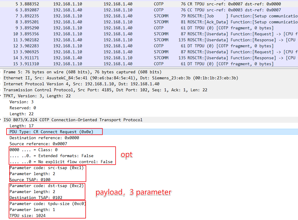
COTP Connection Packet
- COTP Connection Request Packet
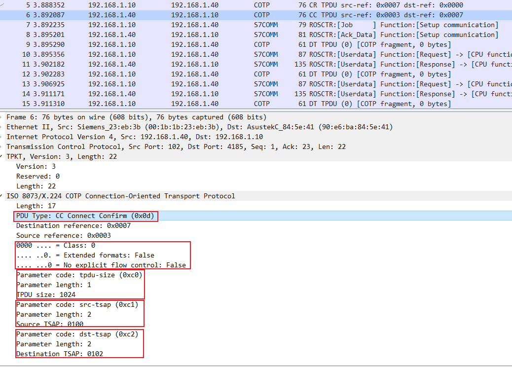
- COTP Request Confirmation Packet
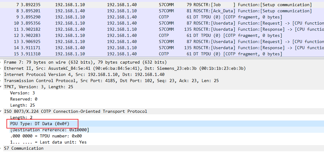
COTP Function Packet
- Data Transfer Packet
S7Comm Header
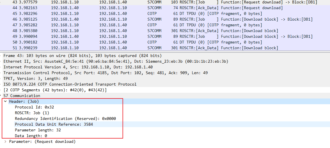
The most critical field is ROSCTR, which determines the structure of subsequent parameters.
In response packets, there may also be error information.
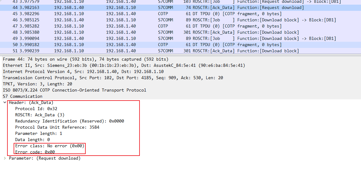
The error type shown in the diagram is No error
Job and Ack_Data
In S7Comm, the first field in the Parameter entry of Job (job request) and Ack_Data (acknowledgment data response) is function (function code), which is an Unsigned integer, size 1 byte, determining the structure and purpose of the remaining fields.
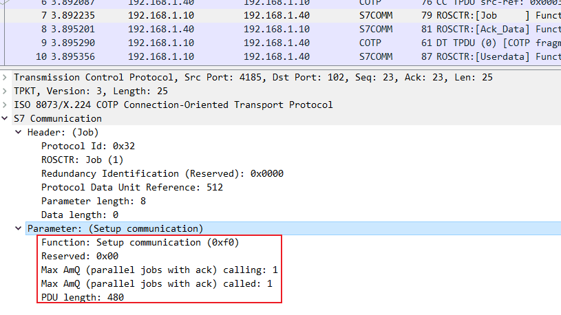
Setup Communication (Setup communication 0xF0)
Establishing communication is sent at the beginning of each session, after which any other messages can be exchanged. It is used to negotiate the size of the ACK queue and the maximum PDU length, with both parties declaring their supported values. The length of the ACK queue determines the number of parallel jobs that can be initiated without requiring acknowledgment. The PDU and queue length fields are big endian.
When the PDU type is Job, the specific Parameter structure is as follows:
- 1 (Unsigned integer, 1 byte): Parameter part: Reserved byte in communication setup pdu, reserved byte;
- 2 (Unsigned integer, 2 bytes): Max AmQ (parallel jobs with ack) calling;
- 3 (Unsigned integer, 2 bytes): Max AmQ (parallel jobs with ack) called;
- 4 (Unsigned integer, 2 bytes): Parameter part: Negotiate PDU length. Negotiate PDU length.
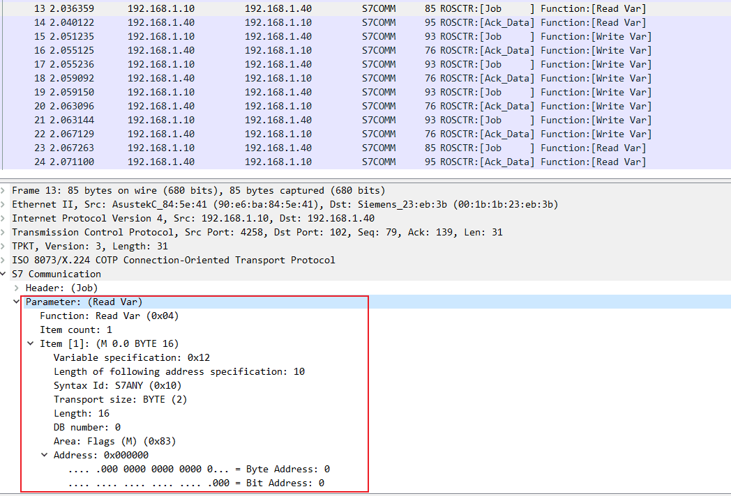
Read Value (Read Var 0x04)
Data read and write operations are executed by specifying the storage area, address (offset), and size or type of the variable.
When the PDU type is Job, the structure of the item is as follows:
- 0 (Unsigned integer, 1 byte): Variable specification, determining the primary type of the item structure, usually 0×12, representing a variable specification;
- 1 (Unsigned integer, 1 byte): Length of following address specification, length of the remaining part of this item;
- 2 (Unsigned integer, 1 byte): Syntax Ids of variable specification, determining the addressing mode and format of the remaining item structure;
- 3(Unsigned integer, 1 byte): Transport sizes in item data, determining the type and length of the variable:
- 4~5 (Unsigned integer, 2 byte): Request data length, length of requested data;
- 6~7 (Unsigned integer, 2 byte): DB number, DB module number, if not accessing the DB area, this is 0×0000;
- 8 (Unsigned integer, 1 byte): Area, area type:
- 9~11 (Unsigned integer, 3 byte): Address, Address.
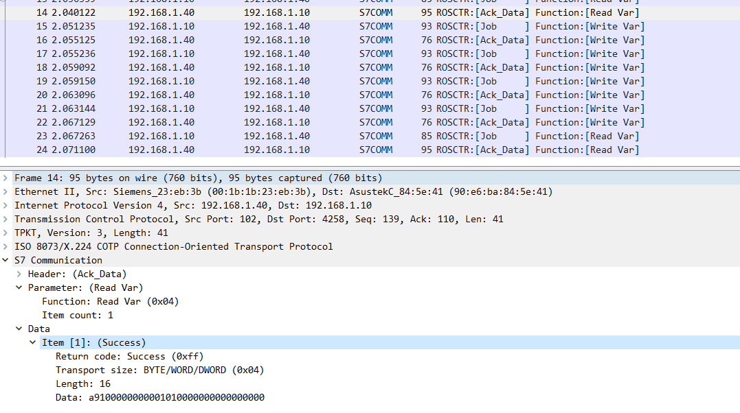
When the PDU type is Ack_Data, the Data structure is as follows:
- 0 (Unsigned integer, 1 byte): Return code,
- 1 (Unsigned integer, 1 byte): Transport size,
- 2~3 (Unsigned integer, 2 bytes): Length,
- 4~4+length (?): Data,
- ? (Unsigned integer, 1 byte): Fill byte,
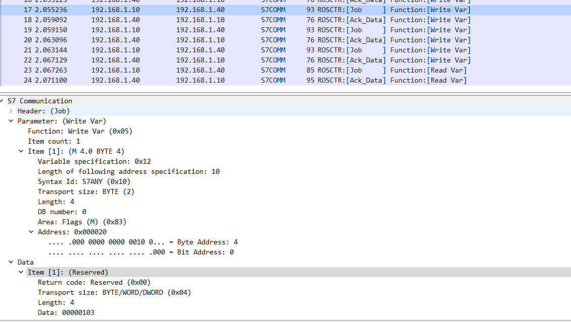
Write Var (Write Var 0x05)
The structure of Write Var’s Parameter is similar to that of Read Var 0x04, but Write Var requires writing a value, so Write Var includes an additional Data entry.
The structure of Data is as follows:
- 0 (Unsigned integer, 1 byte): Return code, return code, undefined here, so Reserved (0×00);
- 1 (unsigned integer, 1 byte): Transport size, determining the type and length of the variable:
- 2-3 (unsigned integer, 2 bytes): Length, length of the data to be written;
- 4 (1 byte): Data, value to be written;
- 5 (unsigned integer, 1 byte): Fill byte, fill byte, if the length of the data is less than Length, it is filled;
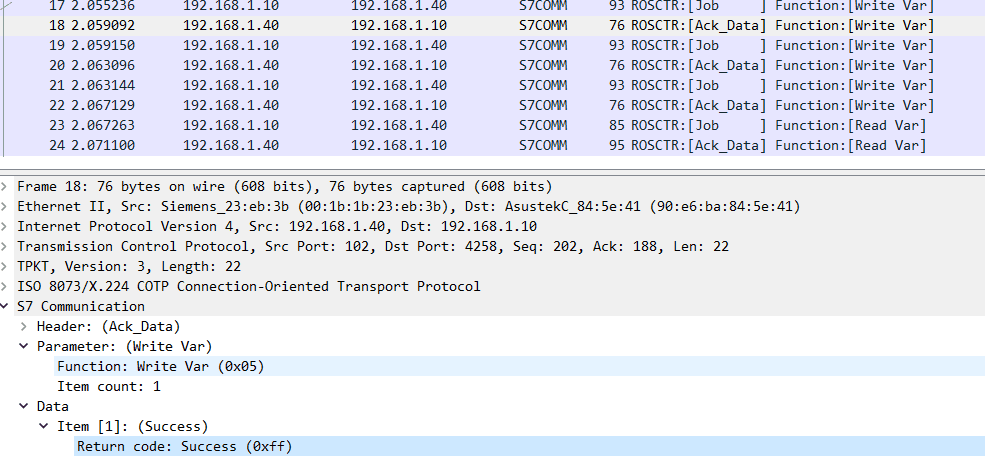
When the PDU type is Ack_Data, the Parameter has only function and item count fields. The Data also has only one Return code field, structured as follows:
- 0 (Unsigned integer, 1 byte): Return code,
Download
Downloading means Step7 sends block data to the PLC. In Siemens devices, the program code and (most) program data are stored in blocks, which have their headers and encoding formats.
There are 8 different types of function blocks in Siemens devices, addressed with special ASCII filenames during upload/download requests. The structure of the filename is as follows:
- 1 (1 byte): File identifier (ASCII), file identifier. There are two file identifiers: _ (Complete Module), $ (Module header for uploading);
- 2 (2 bytes): Block type, Block type.
- 3 (5 bytes): Block number, Block number;
- 4 (1 byte): Destination filesystem(ASCII), destination file system. There are three file systems:
- P (Passive (copied, but not chained) module): passive file system
- A (Active embedded module): active file system
- B (Active as well as passive module): both active and passive file system
There are three different function types for downloading:
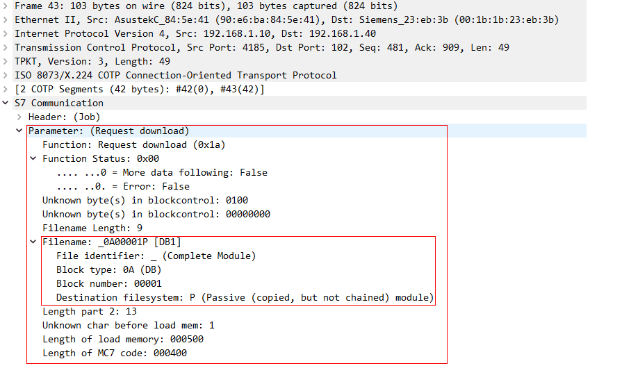
- Request download (Request download 0x1A)
When the PDU type is Job, Request download 0x1A has no Data, and its Parameter structure is as follows:
- 1 (1 byte): Function Status,
- 2 (2 bytes): for all unknown bytes in blockcontrol;
- 3 (4 bytes): meaningless, generally 0x00000000;
- 4 (1 byte): filename length, length of the filename;
- 5 (? bytes): filename, default is 9 byte, filename, usually 9 bytes in length;
- 1 (1 byte): File identifier (ASCII), file identifier. With two identifiers: _ (Complete Module), $ (Module header for uploading);
- 2 (2 bytes): Block type, Block type.
- 3 (5 bytes): Block number, Block number;
- 4 (1 byte): Destination filesystem (ASCII), destination file system. There are three file systems: P (Passive (copied, but not chained) module), A (Active embedded module), B (Active as well as passive module);
- 6 (1 byte): Length part 2 in bytes, length of the second part of the parameter, which is the length of the following fields;
- 7 (1 byte): Unknown char (ASCII);
- 8 (6 bytes): Length load memory in bytes (ASCII);
- 9 (6 bytes): Length of MC7 code in bytes (ASCII).
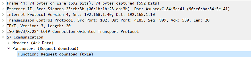
When the PDU type is Ack_Data, the Parameter of Request download 0x1A only contains one function.
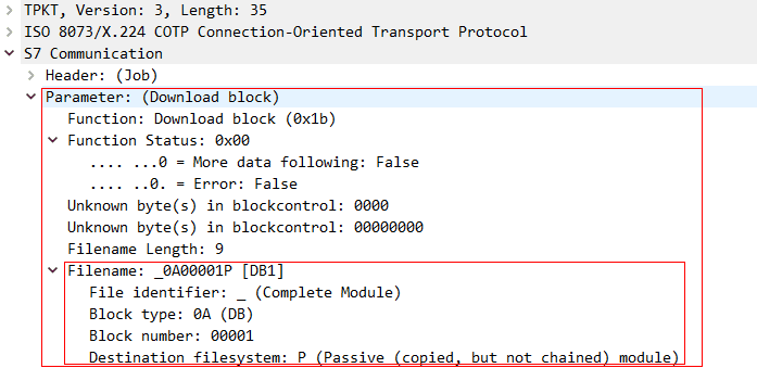
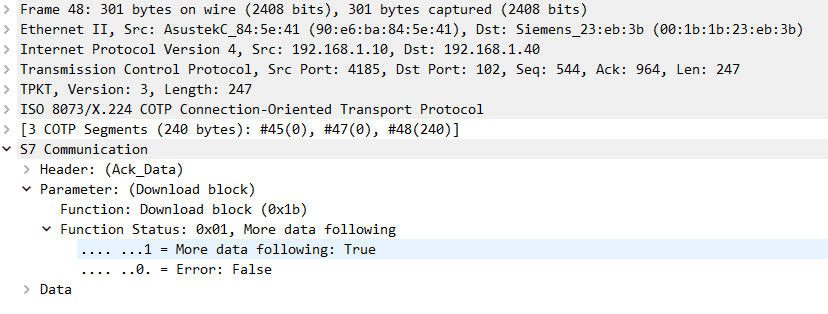
- Download block (Download block 0x1B)
Downloading means Step7 sends block data to the PLC. When the PDU type is Job, Download block 0x1B also has no Data, and its Parameter structure is as follows:
- 1 (1 byte): Function Status,
- 2 (2 bytes): for all unknown bytes in blockcontrol;
- 3 (4 bytes): meaningless, generally 0x00000000;
- 4 (1 byte): filename length, length of the filename;
- 5 (? bytes): filename, default is 9 byte, filename, usually 9 bytes in length;
- 1 (1 byte): File identifier (ASCII), file identifier. With two identifiers: _ (Complete Module), $ (Module header for uploading);
- 2 (2 bytes): Block type, Block type.
- 3 (5 bytes): Block number, Block number;
- 4 (1 byte): Destination filesystem (ASCII), destination file system. There are three file systems:
The first part of Parameter for Download block 0x1B is the same as that for Request download 0x1A.
When the PDU type is Ack_Data, Download block 0x1B has both Parameter and Data. The Parameter structure is as follows:
- 1 (1 byte): Function Status,
- 1 (Unsigned integer, 2 bytes): Length, data length;
- 2 (Unsigned integer, 2 bytes): Unknown byte(s) in blockcontrol, unknown bytes;
- 3 (Label, data_length-4 bytes): Data, Data;
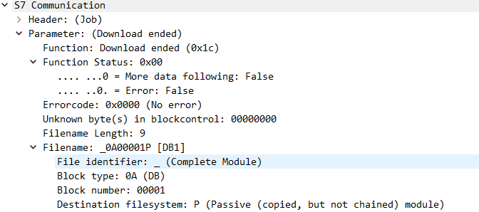
- Download ended (Download ended 0x1C)
When the PDU type is Job, Download ended 0x1C also has no Data. Its Parameter structure is as follows:
- 1 (1 byte): Function Status,
- 2 (2 bytes): for all unknown bytes in blockcontrol;
- 3 (4 bytes): meaningless, generally 0x00000000;
- 4 (1 byte): filename length, length of the filename;
- 5 (? bytes): filename, default is 9 byte, filename, usually 9 bytes in length;
- 1 (1 byte): File identifier (ASCII), file identifier. With two identifiers: _ (Complete Module), $ (Module header for uploading);
- 2 (2 bytes): Block type, Block type.
- 3 (5 bytes): Block number, Block number;
- 4 (1 byte): Destination filesystem (ASCII), destination file system. There are three file systems:
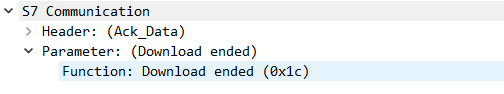
When the PDU type is Ack_Data, the Parameter of Download ended 0x1C only contains one function.
Upload
Uploading means the PLC sends block data to Step7.
During the upload process, first, Step7 sends a start upload job to the PLC. Upon receipt, the PLC replies with Ack_Data, informing Step7 of the block length and the upload session ID. Then, the PLC continues to upload block data to Step7 until Step7 receives all bytes. Finally, Step7 sends a job request to end the upload, closing the upload session.
Uploading involves three different function types:
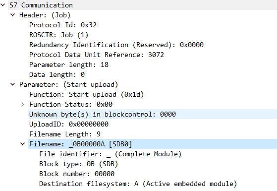
- Start upload (Start upload 0x1D)
When the PDU type is Job, Start upload 0x1D has no Data, and its Parameter structure is as follows:
- 1 (1 byte): Function Status,
- 2 (2 bytes): for all unknown bytes in blockcontrol;
- 3 (4 bytes): upload session ID, initially 0x00000000;
- 4 (1 byte): filename length, length of the filename;
- 5 (? bytes): filename, default is 9 byte, filename, usually 9 bytes in length;
- 1 (1 byte): File identifier (ASCII), file identifier. With two identifiers: _ (Complete Module), $ (Module header for uploading);
- 2 (2 bytes): Block type, Block type.
- 3 (5 bytes): Block number, Block number;
- 4 (1 byte): Destination filesystem (ASCII), destination file system. There are three file systems:
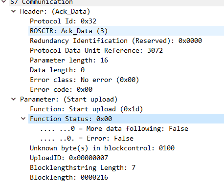
When the PDU type is Ack_Data, the structure of its Parameter for Start upload 0x1D is as follows:
- 1 (1 byte): Function Status,
- 2 (2 bytes): for all unknown bytes in blockcontrol;
- 3 (4 bytes): upload session ID, informing Step7 of the upload session ID;
- 4 (Unsigned integer, 1 byte): Blocklengthstring Length;
- 5 (Character string): Blocklength,
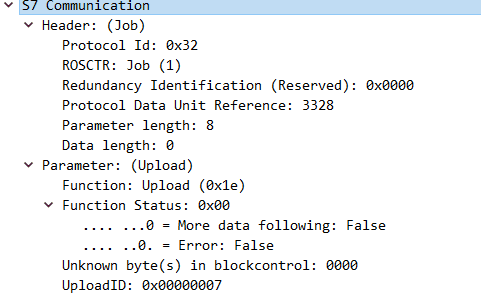
- Upload (Upload 0x1E)
When the PDU type is Job, Upload 0x1E also has no Data, and its Parameter structure is as follows:
- 1 (1 byte): Function Status,
- 2 (2 bytes): for all unknown bytes in blockcontrol;
- 3 (4 bytes): upload session ID, informing Step7 of the upload session ID;
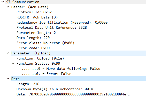
When the PDU type is Ack_Data, Upload 0x1E has both Parameter and Data. Its Parameter structure is as follows:
- 1 (1 byte): Function Status,
- 1 (Unsigned integer, 2 bytes): Length,
- 2 (Unsigned integer, 2 bytes): Unknown byte(s) in blockcontrol,
- 3 (Label, data_length-4 bytes): Data,
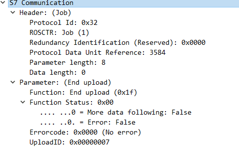
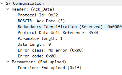
- End upload (End upload 0x1F)
The process of ending an upload is that after all data is uploaded, Step7 sends a job request to end the upload, and upon receipt, the PLC closes the session and returns a response.
When the PDU type is Job, End upload 0x1F also has no Data, and its Parameter structure is as follows:
- 1 (1 byte): Function Status,
- 2 (2 bytes): Error code,
- 3 (4 bytes): upload session ID, informing Step7 of the upload session ID; When the PDU type is Ack_Data, End upload 0x1F’s Parameter only contains one function.
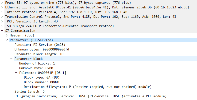
PI service 0x28
Program Invocation is used for routine operations on the PLC that modify execution/memory status. These commands can be used to start or stop PLC control programs, activate or delete program blocks.
When the PDU type is Job, PI service 0x28 has no Data, only Parameter, and the Parameter structure is as follows:
- 1 (7 bytes): Unknown,
- 2 (Unsigned integer, 2 bytes): Parameter block length,
- 3 (?bytes): Parameter block,
- 4 (Unsigned integer, 1 byte): String length, length of the PI service string;
- 5 (Character string, ASCII): PI (program invocation) Service name,
Parameter contains two main parts:
- Service Name
- Parameters: depending on the method type, they can be regarded as its arguments
Examples of service names and their related parameters:
- _INSE: Activates blocks downloaded on the device, the parameter is the block name (e.g., OB 1).
- _DELE: Deletes a block from the device’s file system, the parameter is also the block name.
- P_PROGRAM: Sets the device’s operating status (start, stop, reset).
- _GARB: Compresses the PLC memory.
- _MODU: Copies ram to ROM, the parameter contains the file system identifier (A/E/P).
If the parameter for a PI service is a block, the structure of the Parameter block is as follows:
- 1 (1 byte): Number of block,
- 2 (1 byte): Unknown, default 0x00;
- 3 (? bytes): filename, filename:
- 1 (2 bytes, ASCII): Block type,
- 2 (5 bytes, ASCII): Block number,
- 3 (1 byte, ASCII): Destination filesystem (ASCII), destination file system. There are three file systems: P (Passive (copied, but not chained) module), A (Active embedded module), B (Active as well as passive module);
PLC STOP 0x29
PLC STOP is essentially the same as program invocation service (PI service 0x28), except it has no Parameter block, and its PI service is P_PROGRAM.
Traffic Packet Analysis
Download the pcap packet released on the Wireshark official site https://wiki.wireshark.org/SampleCaptures?action=AttachFile&do=get&target=s7comm_varservice_libnodavedemo.pcap
Setup Communication (Setup communication 0xF0)
- Request
- Response
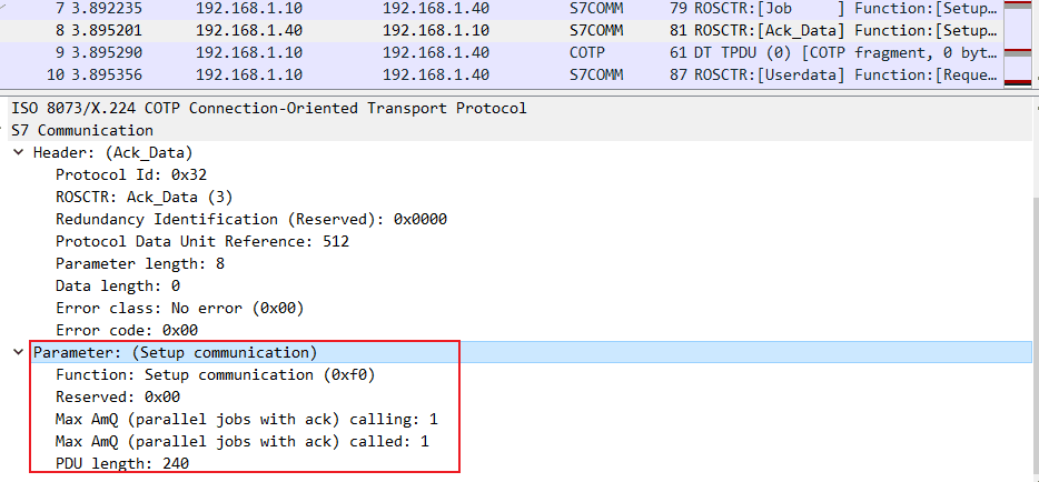
The negotiation result is: ACK queue size is 1; maximum PDU length is 240.
Request Download (Request download 0x1A)
- Request
- Response
Download Block (Download block 0x1B)
- Request
- Response
Download Ended (Download ended 0x1C)
- Request
- Response
Program Invocation Service (PI service 0x28)
- Request
- Response

Then download this traffic packet https://github.com/ITI/ICS-Security-Tools/blob/master/pcaps/s7/snap7_s300_everything.pcapng
Start Upload (Start upload 0x1D)
- Request
- Response
Upload (Upload 0x1E)
- Request
- Response
End Upload (End upload 0x1F)
- Request
- Response
Then download this traffic packet https://wiki.wireshark.org/SampleCaptures?action=AttachFile&do=get&target=s7comm_varservice_libnodavedemo.pcap
Read Value (Read Var 0x04)
- Job request for value reading operation
- Response
Write Value (Write Var 0x05)
- Job request writing to address 0×000020 Flags (M) with 0×0103
- Acknowledgment response writing to address 0×000020 Flags (M) with 0×0103
Summary
In this article, we analyzed the S7comm protocol’s S7Comm Header, Job, and Ack_Data mechanisms and conducted packet capture analysis of their request and response messages using Wireshark. In the next article, we will continue to learn about the S7comm protocol’s Userdata protocol extension part.