
Wireshark Packet Capture Experiment
1.1 Learn the basic operations of the Wireshark tool
Learn the settings and use of capture options, such as considering the source host and destination host, setting the Capture Filter correctly; setting the Display Filter after capture.
1.2 Network packet capture analysis of the PING command
The PING command works based on the ICMP protocol, sending 4 packets, normally returns four packets. Taking host 210.31.40.41 as an example, the main experimental steps are:
(1) Set “Capture Filter”: Fill in host 210.31.40.41 in the Capture Filter;
(2) Start capturing packets;
(3) Execute the PING command in DOS;
(4) Stop capturing packets.
(5) Set “Display Filter”: IP.Addr=210.31.40.41
(6) Select a data packet, focus on analyzing its protocol part, especially the protocol header content, click on all content marked with a + sign.
(7) Capture screenshots of key content and analyze the content in the protocol fields, and write them in a WORD document.
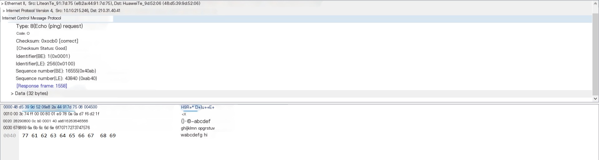
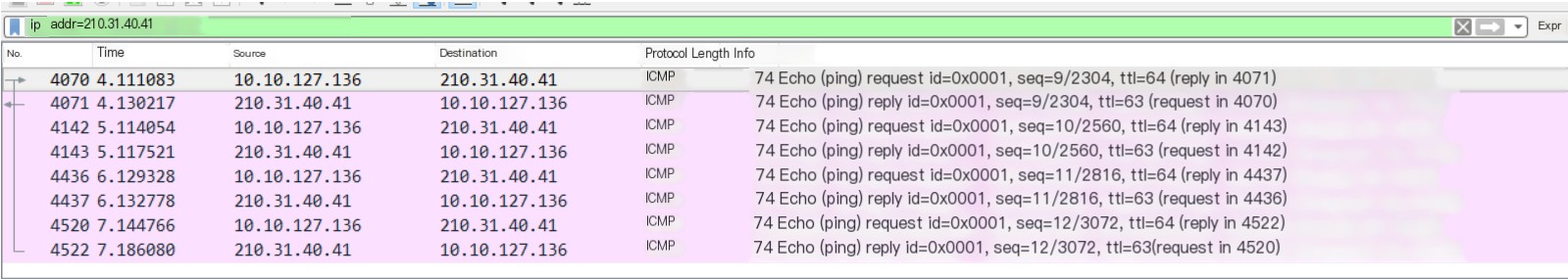
Through simple analysis, we can see that the Ping command uses the ICMP protocol. For each packet sent to 210.31.40.41, a packet is received as well. A total of four packets were sent and received, as shown. Analyzing one of the packets, you can see its type length is 8, and the data length is 32 bytes, see the picture
1.3 Data Capture for the TRACERT Command
Observe the routing hop process. Independently select two target hosts, one inside the school network and one outside, for example,
(1) Inside the school: tracert 210.31.32.8
First, before executing the tracert command, filter and select the relevant requests of 210.31.32.8 in Wireshark. Then press win+r to open the cmd interface and execute the tracert command
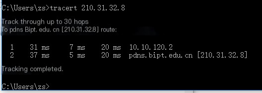
The captured data is shown below,
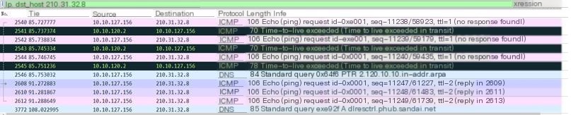
Through simple analysis of the packet capture results, it can be seen that the captured protocol types mainly include ICMP and DNS protocols. View their specific content by selecting different types of protocols.
DNS Protocol:
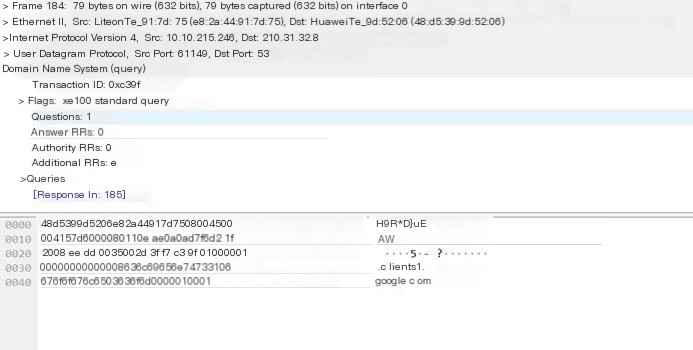
Through a simple look at the above picture, it can be known that the DNS protocol operates from 10.10.215.246 to 210.31.32.8, also including the UDP protocol, with a source port of 61149 and a destination port of 53. DNS conducted 84 standard queries for the domain name 210.31.40.41, clearly visible in the DNS transaction ID: 0xc39f, the query result in the DNS server is in line 185.
ICMP Protocol:
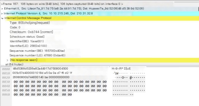
The content of the ICMP was analyzed earlier, so it will not be repeated here. From the comparison in the picture, it can be seen that the data length of the data has changed to 64 bytes.
(2) Outside the school: tracert www.sogou.com

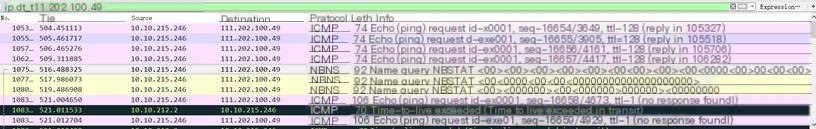
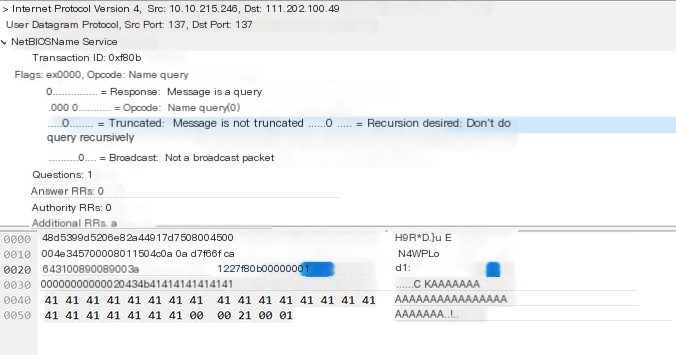
Through simple analysis, it can be seen that when packet capturing Sogou, two types of protocols appear, ICMP and NBNS, where the NBNS protocol is a part of the NetBIOS protocol suite on TCP/IP, providing hostname and address mapping methods on networks accessed based on NetBIOS name.
1.4 Port Scan Data Capture and Analysis
(1) Each group independently downloads and installs a port scanning tool, such as NMAP, SUPERSCAN, SCANPORT,
SSPORT, TCPVIEW.
(2) Scan the host of the other party, obtain open port numbers. Capture all related information and protocol content. Example of display filter:
Here, Zenmap is used to perform a port scan on the local machine, and the scan results are as shown below.
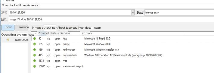
It can be seen that the local machine has 6 open ports, different ports providing different services. One of them, port 80, is for the HTTP service, indicating the deployment of a self-hosted website using port 80.
View the packet capture situation of this port in Wireshark
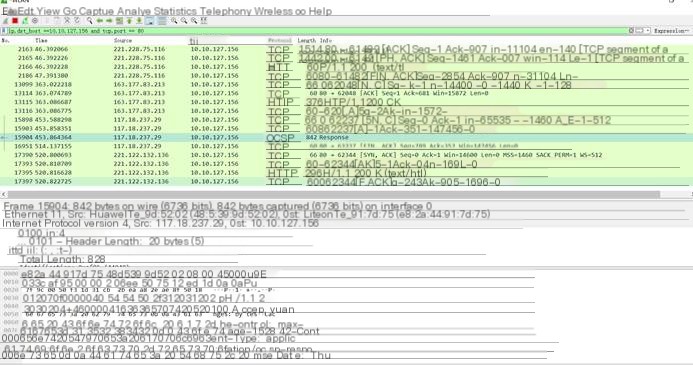
From the picture, two protocols are seen, TCP and HTTP, which also confirms the previous statement about website deployment.
(3) Close an open port, rescan, and observe the capture effect.
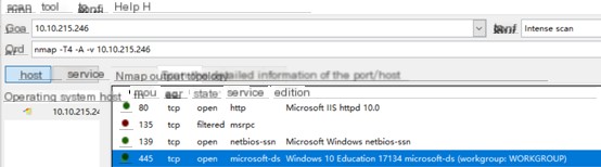
After closing the port and scanning, it can be seen that the closed port is not detectable anymore.
1.5 FTP Protocol Packet Capture and Analysis
Log in to the FTP server: ftp.scene.org, focus on capturing its 3 key processes:
(1) FTP server login
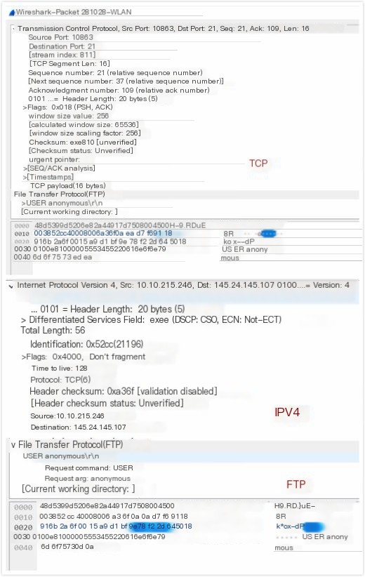
Capture the content of USER and PWD, analyze the header information of FTP, TCP, and IP protocols. The port number of the FTP server is 21, used for control connection.
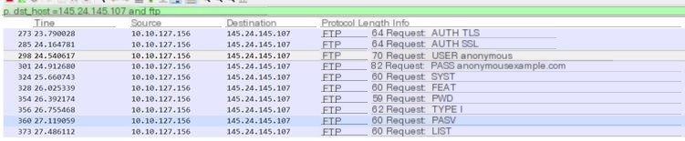
Here, filezilla is used to log in to the FTP server. Capturing the login process shows the login account is anonymous, and the password is [email protected] (default).
View the header information of the FTP, TCP, and IP protocols in Wireshark, as shown below.
(2) FTP File Download Process
Request to download three files of different sizes (less than 1MB, 1MB-10MB, more than 10MB), observe the data sharding process in FTP, TCP, and IP protocols.
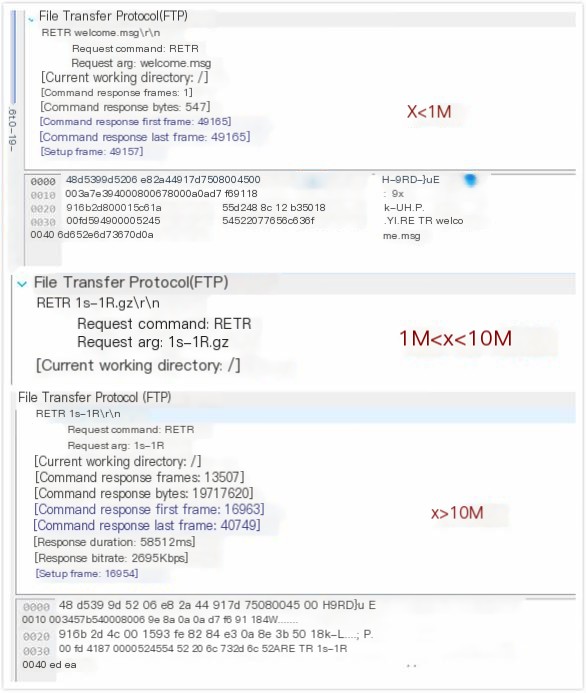
In Figure 5-3, it can be seen that the request command for the download file is “RETA”, and the size of the file bytes is different.
Differences can also be seen from the sending time. Files between 1MB and 10MB might not display the packet size and transmission time normally due to their format or other reasons. However, by comparing different file sizes, it can be concluded that the larger the file size, the smaller the TCP slice length, the more bytes are transmitted, and the longer it takes to transmit.
(3) FTP Service Exit Process
Analyze the different contents of FTP, TCP, and IP protocols.
The exit process of FTP was not captured in Wireshark’s packet capture process.
1.6 HTTP Protocol Packet Capture and Analysis
Log in to some domestic and international portal sites, capture the homepage browsing process, and analyze the contents of their HTTP, TCP, UDP, and IP protocols. Pay attention to the port numbers in the TCP protocol.
Supplement the workflow of HTTP:
(1) The client establishes a connection with the server through a three-way handshake.
(2) After the TCP connection is successfully established, an http request is sent to the server.
(3) After receiving the http request from the client, the server will respond and send data to the client.
(4) The client disconnects the TCP connection with the server through a four-way handshake.
Domestic website:
Here we take JD Mall as an example jd.com (111.13.28.118), capture the homepage browsing process, and the packet capture result is as shown. From the picture, it can be seen that the TCP handshake was conducted at No 1950, 1951, and 1958, using port 80 of the TCP protocol. (Note: Wireshark can only capture HTTP; it cannot decrypt or recognize HTTPS. Most domestic websites’ main pages are http; only the login interface or a few homepages are encrypted with https. However, to obscure it, most website headers begin with https, even if they do not serve any purpose.)
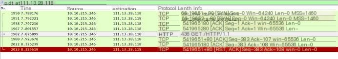
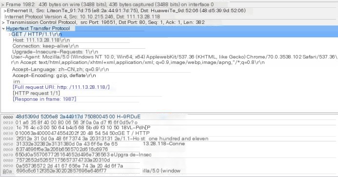
From packet data, it can be analyzed (see Figure 6-2), the local machine’s address is 10.10.215.246, the capture port is 19651. The target address is 111.13.28.118, the open port is 80, the TCP protocol data slice length is 382. Look at the HTTP protocol, where the HTTP request header is Mozilla/5.0 (Windows NT 10.0; Win64; X64)… and its accepted language is Chinese, etc., which is some of the data sent to the server when accessing the URL normally.
1.7 EMAIL Protocol Packet Capture and Analysis
Log into the internal and external email systems, capture your own login information, and focus on analyzing the contents of the SMTP and POP3 protocols. Note their port numbers are 25 and 110, respectively.
Most email uses SSL encryption now, that is the https protocol, with common ports like 80 for HTTP and port number 443 for HTTPS. Here, I am using the foxmail client to capture EMAIL protocol packets, the captured content is shown below
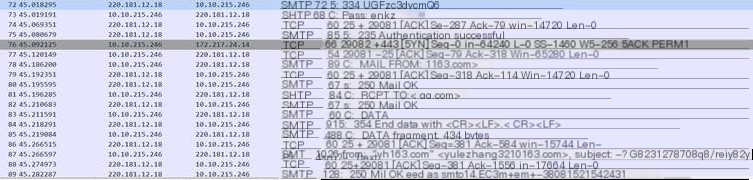
In the Protocol column, you can see protocols like TCP and SMTP displayed. Since SMTP is based on the TCP protocol, you must establish a TCP connection through a three-way handshake before using the SMTP protocol to send emails. From the third-to-last SMTP packet, you can see the email account used to send the email. Frame 75 indicates successful login to the email account, Frame 78 shows the sending email account, in this case, ****@qq.com. Frame 81 represents the receiving email account, in this case using qq mail as an example. Frame 83 is the content sent by the client, while Frame 84 shows the received text.
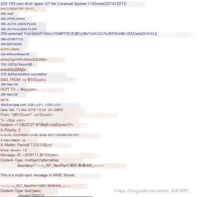
This interface clearly shows the email information (right-click an SMTP packet, select follow->TCP Stream to view), the red part is the client sending information, and the blue part is the server’s response information. In this interface, you can see the client’s host name, email account, email client used, email content type, and transmission format, etc. You can also see the sent content which is encrypted as base64 format information.
Four, Discussion Questions
(1) In the FTP service, why is the FTP data length 1460 bytes?
The maximum transmission unit is 1460 bytes, which is the length limit for a TCP segment.
(2) How to capture the ending data packet of the FTP service?
Enter ftp into the filter, and you will see “Request: QUIT” in the Information column, indicating the end package of FTP.
(3) In port scanning, the corresponding protocols are TCP and UDP. How should you find the service type corresponding to a certain port?
Use the netstat -a -n command in the cmd command line to view.
(4) Why cannot some neighboring hosts capture when IP address is not specified?
Each packet can be sent through different paths over the network, and packets can arrive in a different order than they were sent. The network protocol (IP) only delivers them, and TCP can combine them back in the correct order. IP is a connectionless protocol, meaning no continuous line connection exists between the endpoints of communication, leading to some hosts not being able to capture the information.
(5) Why is the ARP protocol data packet captured operation when using the PING command?
Because ARP protocol stands for “Address Resolution Protocol”. In a local area network, frames are actually transmitted, and the destination host’s MAC address is included in the frame. The basic function of the ARP protocol is to query the MAC address of the target device through the IP address of the target device to ensure smooth communication.