
While using Google to search for study materials, I came across a book titled “Circles Teach You to Play with USB.” During the reading, I found that I needed to purchase related hardware devices.
The hardware development section will be considered for later content learning and research. Initially, the focus will be on using the existing devices on hand for study and research purposes. First, the consideration is to use a smartphone as a USB device connected to a computer. However, after research, it became evident that Android’s support for USB device development is not very friendly. Additionally, encapsulating USB development at the Android layer makes understanding the underlying USB details challenging for us.
Subsequently, considering that I have a Raspberry Pi 4B device at hand, I decided to attempt using this device for USB development. After conducting a Google search, I discovered a project called key-mime-pi, which can serve as a starting point for my introduction.
1 Tools Related to USB Device Development
References
After some research, since the tools related to USB on Windows are better visualized, I ultimately chose a Windows device as the USB host.
1.1 USB Tree View
The first tool is USB Tree View, which can effectively display the master-slave relationships of USB devices on the host, USB descriptor information, and other data. As shown in Figure 1:
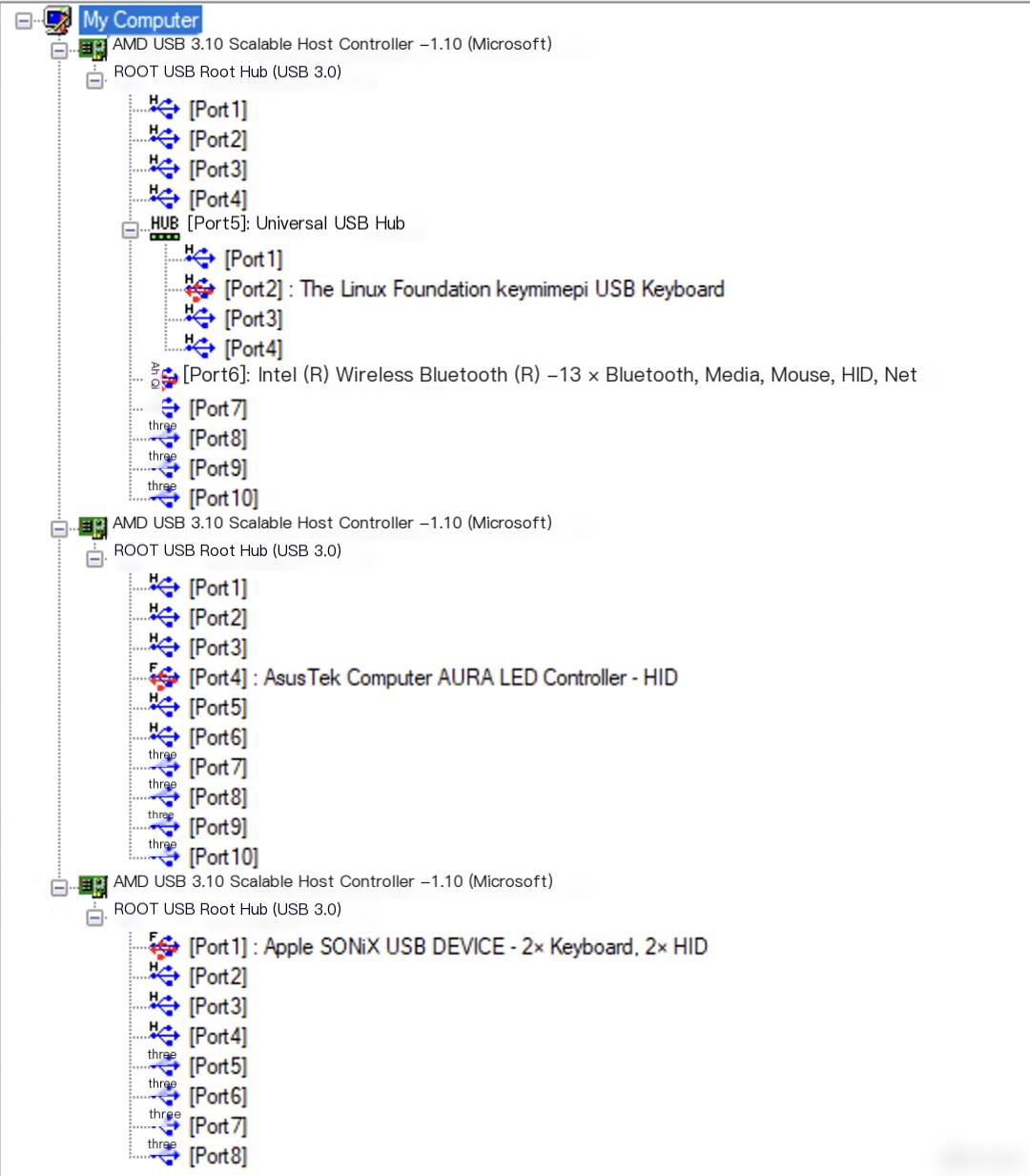
Figure 1: USB Tree View Interface
From the USB device tree shown above, it can be seen that the lowest layer in a host is the USB host controller, which directly connects to the CPU. The next layer up is the USB root hub (HUB), which can be likened to a USB docking station. Its function is to expand into multiple USB ports, but the total bandwidth is still determined by the USB host controller.
For example, in the image above, if the version of the USB host controller is USB 3.1, then the upper layer USB root hub can branch out into USB 3.1 and lower ports, such as USB 2.0 ports. However, no matter how many USB ports are extended, the total bandwidth remains fixed at 10Gbps (since the bandwidth of USB 3.1 is 10Gbps). Moreover, you can connect multiple hubs to the main hub, as illustrated by the generic USB hub depicted above, which essentially represents the USB interfaces expanded from the computer case on the demo host.
Additionally, by clicking on a connected USB device, you can view more detailed information about that USB device, as shown in Figure 2:
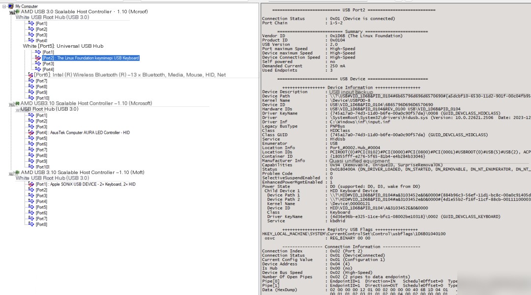
Figure 2: Viewing USB device details in USB Tree View
If you understand the information in the image above, further explanations will be provided later. However, this tool has some bugs; it cannot properly parse HID information, as shown in Figure 3.
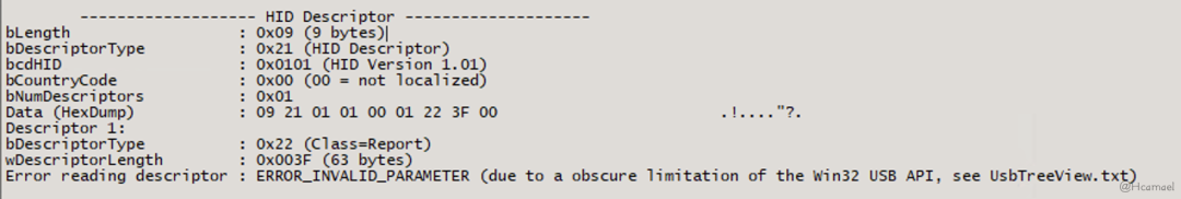
图3:HID Descriptor
1.2 Wireshark
On Windows, with USBPcap installed, Wireshark can capture USB traffic on the host controller. For instance, if there are three host controllers on the host machine, Wireshark will display three USBPcap interfaces, as shown in Figure 4:

Figure 4: Wireshark Interface
If you are unsure which host controller a USB port belongs to when you plug in a USB device, you can use USBTree View to check. However, since Wireshark captures traffic on the host controller, and a single USB host controller can connect to multiple USB devices, when I want to study a specific USB device, I need to use Wireshark’s filter expressions to filter out the traffic from other USB devices connected to that host controller.
1.3 Bus Hound
Bus HoundIt can capture the traffic of a specified USB device. However, this tool has the drawback of requiring payment, otherwise, the size and number of captured packets are limited. A cracked version of this software has yet to be found. Figure 5 shows the interface of this software:
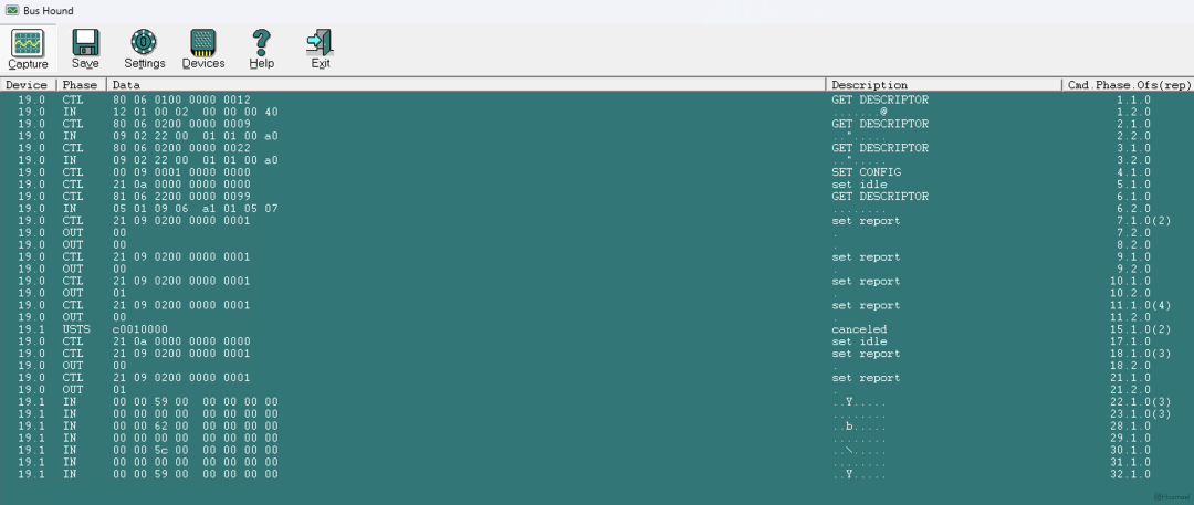
Figure 5: Bus Hound Interface
2 Using Raspberry Pi 4B as a USB Keyboard for PC
Reference material
Next, by readingkey-mime-piThe source code of the project reveals that simulating a USB device using a Raspberry Pi 4B is quite straightforward. Based on the project’s code, the process can be broken down into the following two steps:
1. You need to enable the dwc2 driver: Add the line in the Raspberry Pi’s config.txt file.dtoverlay=dwc2After the device starts, confirm whether the startup has been enabled:
$ lsmod|grep dwc2
dwc2                  196608  0
Execute as shown belowbashIt seems you’ve encountered a script or code. My specialty is translating WordPress post content and ignoring code or structure. Please provide the text you would like translated, and I’ll be glad to assist with that while maintaining the integrity of any existing formatting or styles.
#!/usr/bin/env bash

# Adapted from https://github.com/girst/hardpass-sendHID/blob/master/README.md

# Exit on first error.
set -e

# Treat undefined environment variables as errors.
set -u

modprobe libcomposite

cd /sys/kernel/config/usb_gadget/
mkdir -p g1
cd g1

echo 0x1d6b > idVendor  # Linux Foundation
echo 0x0104 > idProduct # Multifunction Composite Gadget
echo 0x0100 > bcdDevice # v1.0.0
echo 0x0200 > bcdUSB    # USB2

STRINGS_DIR="strings/0x409"
mkdir -p "$STRINGS_DIR"
echo "6b65796d696d6570690" > "${STRINGS_DIR}/serialnumber"
echo "keymimepi" > "${STRINGS_DIR}/manufacturer"
echo "Generic USB Keyboard" > "${STRINGS_DIR}/product"

FUNCTIONS_DIR="functions/hid.usb0"
mkdir -p "$FUNCTIONS_DIR"
echo 1 > "${FUNCTIONS_DIR}/protocol" # Keyboard
echo 0 > "${FUNCTIONS_DIR}/subclass" # No subclass
echo 8 > "${FUNCTIONS_DIR}/report_length"
# Write the report descriptor
# Source: https://www.kernel.org/doc/html/latest/usb/gadget_hid.html
echo -ne \\x05\\x01\\x09\\x06\\xa1\\x01\\x05\\x07\\x19\\xe0\\x29\\xe7\\x15\\x00\\x25\\x01\\x75\\x01\\x95\\x08\\x81\\x02\\x95\\x01\\x75\\x08\\x81\\x03\\x95\\x05\\x75\\x01\\x05\\x08\\x19\\x01\\x29\\x05\\x91\\x02\\x95\\x01\\x75\\x03\\x91\\x03\\x95\\x06\\x75\\x08\\x15\\x00\\x25\\x65\\x05\\x07\\x19\\x00\\x29\\x65\\x81\\x00\\xc0 > "${FUNCTIONS_DIR}/report_desc"

CONFIG_INDEX=1
CONFIGS_DIR="configs/c.${CONFIG_INDEX}"
mkdir -p "$CONFIGS_DIR"
echo 250 > "${CONFIGS_DIR}/MaxPower"

CONFIGS_STRINGS_DIR="${CONFIGS_DIR}/strings/0x409"
mkdir -p "$CONFIGS_STRINGS_DIR"
echo "Config ${CONFIG_INDEX}: ECM network" > "${CONFIGS_STRINGS_DIR}/configuration"

ln -s "$FUNCTIONS_DIR" "${CONFIGS_DIR}/"
ls /sys/class/udc > UDC

chmod 777 /dev/hidg0
By studying the abovebashThe script discovers that the project utilizes the Linux system’s USB gadget driver. If needed, you can view this portion of the source code yourself, located in the Linux kernel at:linux/drivers/usb/dwc2andlinux/drivers/usb/gadgetIn the directory.
The specifics of the driver will not be examined in this article. When executing the abovebashAfter executing the script, and barring any unforeseen issues, you canUSB Tree ViewIn the console, observe the Raspberry Pi device emulating a USB keyboard.
2.1 Understanding USB Protocols through Traffic Re-learning
Here’s a preliminary point: USB follows a host-device architecture, where there is always one USB host and one USB device, and communication is always initiated by the host.
In the context of this post, first open Wireshark and start capturing traffic on USBPcap1. Then connect the Raspberry Pi’s type-c port (the power supply port, as the four USB female ports on the Raspberry Pi 4b device can only function as USB hosts, while only the type-c power supply port can act as a USB device) to the host’s USB port. At this point, the host will not recognize the Raspberry Pi as a USB device and will only supply power, thus the Raspberry Pi will begin to boot.
Then start filtering out all the traffic addresses that Wireshark can capture, as these do not belong to the Raspberry Pi’s USB traffic. As shown in Figure 6, the filtering syntax used in this environment is:
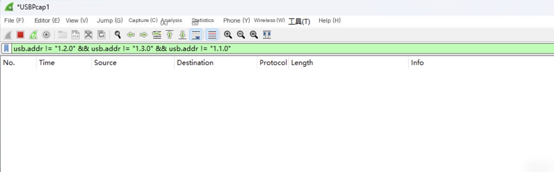
Figure 6: Wireshark Filter Syntax
Then, execute the provided command on the Raspberry Pi with root privileges.bashScript, then examine the traffic captured on Wireshark, as shown in Figure 7:
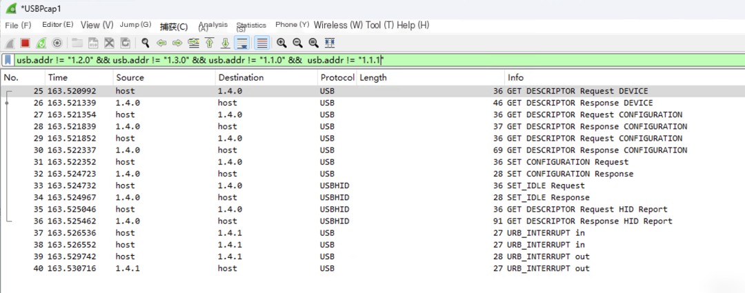
Figure 7: Traffic captured by Wireshark based on the filter syntax
The USB traffic captured using USBPcap generally has the address: x.y.z, where x is the USB Bus number, usually corresponding to the host controller’s number. In the example, the captured USBPcap1 traffic has an x value of 1.
y is the device number, pointing to a specific device on that Bus, butUSBPcapandUSBTreeViewThe method for device numbering is different.USBPcapThe device numbers are defined sequentially, andUSBTreeViewAt the beginning, all USB interfaces have been numbered, regardless of whether a USB device is connected.
According to my understanding,USBPcapMay align more closely with the actual underlying condition, as it is not a self-generated code, but rather an analysis of captured USB traffic.
The value of z represents the endpoint number, which I believe is somewhat akin to a file descriptor (fd) in a program. Communication between a USB host and device is conducted through endpoint numbers. When a USB device is not yet registered on the host, it defaults to using0Endpoint number for communication.
2.1.1 Device Descriptor
Next, researching the USB protocol, it was discovered that USB devices inform the host about their own information by sending various descriptors. These descriptors are defined in the Linux source code through structures, with each structure field’s meaning referable to related articles. Below, we analyze several important USB descriptors.
The first is the device descriptor, and the structure of this descriptor is defined at:linux/include/uapi/linux/usb/ch9.hThe structure is as follows:
/* USB_DT_DEVICE: Device descriptor */
struct usb_device_descriptor {
    __u8  bLength;
    __u8  bDescriptorType;

    __le16 bcdUSB;
    __u8  bDeviceClass;
    __u8  bDeviceSubClass;
    __u8  bDeviceProtocol;
    __u8  bMaxPacketSize0;
    __le16 idVendor;
    __le16 idProduct;
    __le16 bcdDevice;
    __u8  iManufacturer;
    __u8  iProduct;
    __u8  iSerialNumber;
    __u8  bNumConfigurations;
} __attribute__ ((packed));
First, examine the device descriptor captured on USBPcap, as shown in Figure 8:
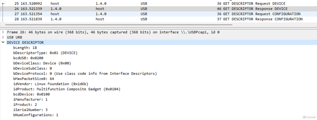
Figure 8: Viewing Device Descriptor on Wireshark
Compare again.USBTree ViewDevice descriptor information displayed as shown in Figure 9:
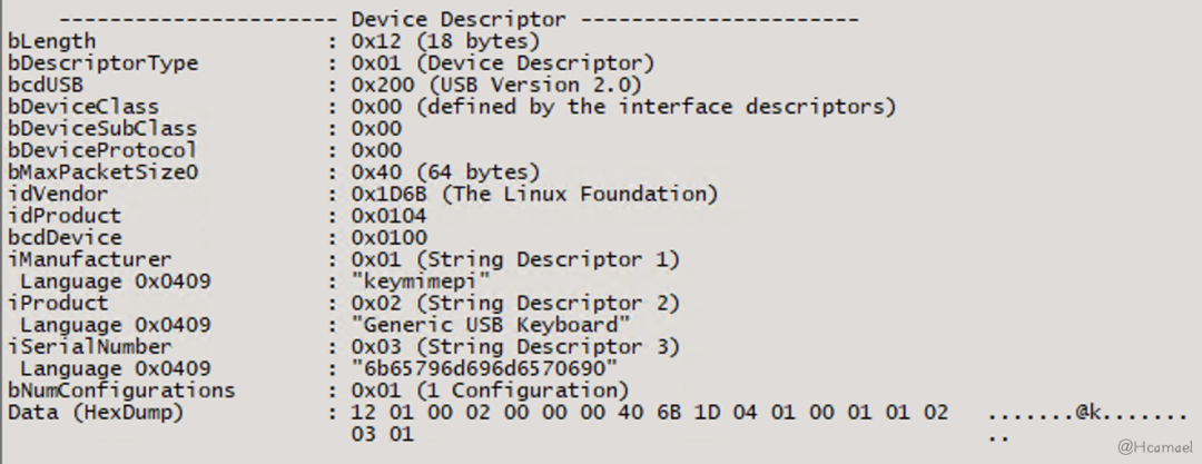
Figure 9: Viewing Device Descriptor in USB Tree View
By comparison, it was found that the control device descriptor is located atbashThe following lines of code in the script:
echo 0x1d6b > idVendor  # Linux Foundation
echo 0x0104 > idProduct # Multifunction Composite Gadget
echo 0x0100 > bcdDevice # v1.0.0
echo 0x0200 > bcdUSB    # USB2

STRINGS_DIR="strings/0x409"
mkdir -p "$STRINGS_DIR"
echo "6b65796d696d6570690" > "${STRINGS_DIR}/serialnumber"
echo "keymimepi" > "${STRINGS_DIR}/manufacturer"
echo "Generic USB Keyboard" > "${STRINGS_DIR}/product"
First, the protocol for the device is defined as USB 2.0, then the Vendor ID (0x1d6b) and Product ID (0x0104) are set, and then it is defined as…bNumConfigurationsSet the number of configuration descriptors to0x01, the remaining parts are just some string identifier information.
In most cases, vendor information acts as identification data, but in subsequent articles, you will find that certain drivers rely on recognizing specific vendor and product IDs to activate. Currently, we’re only simulating mouse/keyboard devices, and they do not depend on these IDs for activation, so they can be freely modified.
The host will then request the number of configuration descriptors specified in the device descriptor from the device.
2.1.2 Configuration Descriptor
The structure definition for the configuration descriptor is as follows:linux/include/uapi/linux/usb/ch9.hThe structure is as follows:
struct usb_config_descriptor {
    __u8  bLength;
    __u8  bDescriptorType;

    __le16 wTotalLength;
    __u8  bNumInterfaces;
    __u8  bConfigurationValue;
    __u8  iConfiguration;
    __u8  bmAttributes;
    __u8  bMaxPower;
} __attribute__ ((packed));
First, review the configuration descriptor captured on USBPcap, as shown in Figure 10:
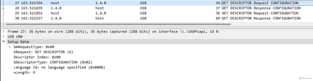
Figure 10: Host-Initiated Request for Configuration Descriptor
The host will first request a configuration descriptor with a fixed length of 9, as shown in Figure 11:
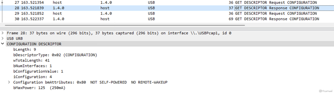
Figure 11: Viewing Configuration Descriptor on Wireshark
Then the host through the configuration descriptor’swTotalLengthField, learn the actual length of the configuration descriptor, then the host will request the complete configuration descriptor from the USB device, as shown in Figure 12 and Figure 13:
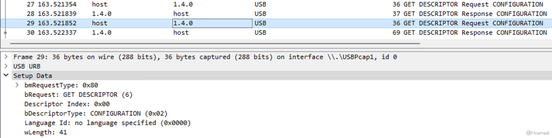
Figure 12: Host-Initiated Request for Fetching Configuration Descriptor
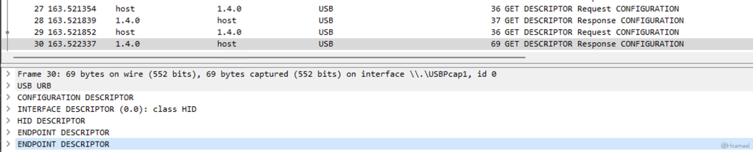
Figure 13: USB Device Response to a Complete Configuration Descriptor Packet
From the traffic captured by USBPcap, it can be observed that the response packet of the configuration descriptor contains not only the information of the configuration descriptor but also includes interface descriptors and endpoint descriptors. Additionally, because the USB keyboard is registered as a USB HID device, the configuration descriptor also includes an HID descriptor, as shown in Figure 14.
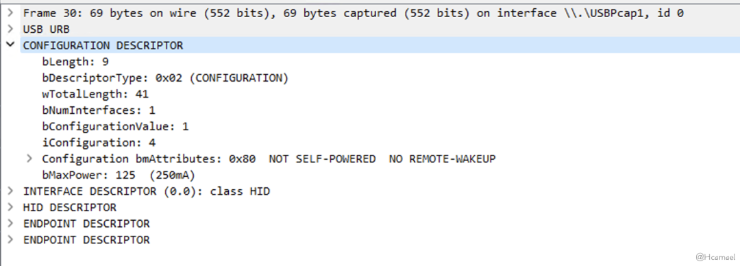
Figure 14: Viewing the Configuration Descriptor in Wireshark
Use USB Tree View to check the configuration descriptor, as shown in Figure 15:
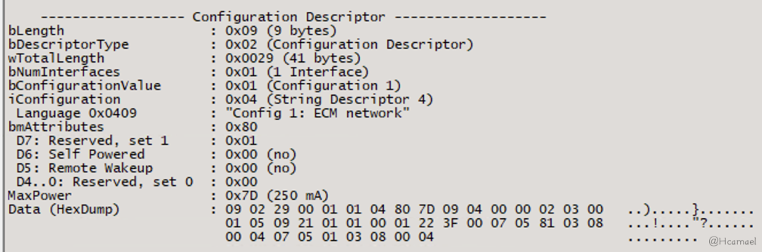
Figure 15: Viewing Configuration Descriptor in USB Tree View
Next, let’s explain a few fields in the configuration descriptor:
bmAttributes: This field pertains to attributes related to power control, indicating to the host device whether it is self-powered or requires USB host power, and whether the device can be remotely awakened through USB.MaxPowerThe purpose of this field is to inform the host of the maximum current the USB device can accept.bNumInterfacesThis field once again informs the host of how many configuration descriptors the USB device has.bConfigurationValueThis value is the index of the configuration descriptor, used inSet Configuration RequestHere, it’s used to notify which USB configuration descriptor has been successfully registered in the host’s kernel.
After analyzing the configuration descriptor, it can be understood that the control configuration descriptor is inbashThe code in the script is shown as follows:
CONFIG_INDEX=1
CONFIGS_DIR="configs/c.${CONFIG_INDEX}"
mkdir -p "$CONFIGS_DIR"
echo 250 > "${CONFIGS_DIR}/MaxPower"
CONFIGS_STRINGS_DIR="${CONFIGS_DIR}/strings/0x409"
mkdir -p "$CONFIGS_STRINGS_DIR"
echo "Config ${CONFIG_INDEX}: ECM network" > "${CONFIGS_STRINGS_DIR}/configuration"
2.1.3 Interface Descriptors
The structure definition for the interface descriptor is:linux/include/uapi/linux/usb/ch9.h, the structure is as follows:
/* USB_DT_INTERFACE: Interface descriptor */
struct usb_interface_descriptor {
    __u8  bLength;
    __u8  bDescriptorType;

    __u8  bInterfaceNumber;
    __u8  bAlternateSetting;
    __u8  bNumEndpoints;
    __u8  bInterfaceClass;
    __u8  bInterfaceSubClass;
    __u8  bInterfaceProtocol;
    __u8  iInterface;
} __attribute__ ((packed));
First, examine the interface descriptors captured on USBPcap, as shown in Figure 16:
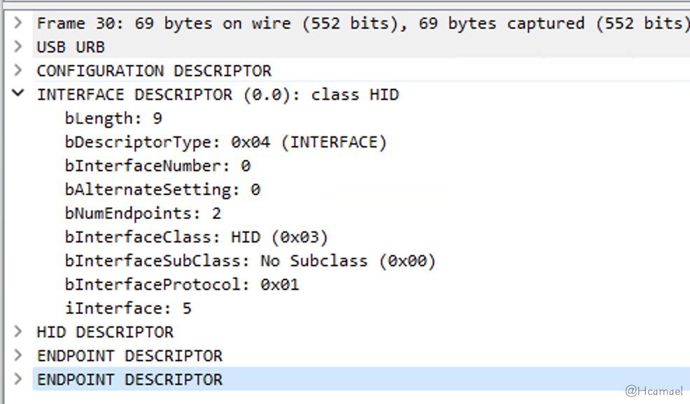
Figure 16: Viewing Interface Descriptors in Wireshark
Review AgainUSBTree ViewThe interface descriptor information, as shown in Figure 17:
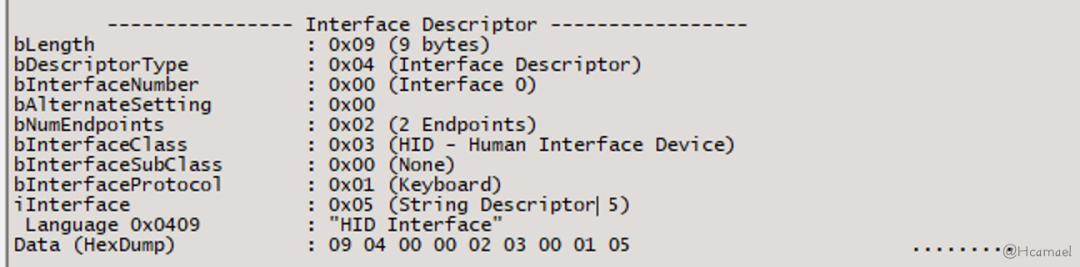
Figure 17: Viewing Interface Descriptors in USB Tree View
In the interface descriptor, the meanings of the fields are as follows:
bNumEndpointsDefined the number of device endpoints. In the USB protocol, endpoint communication is unidirectional. Here, two endpoint descriptors are defined: one represents input, and the other represents output.bInterfaceClassThe type of interface is defined, and in the above diagram, an HID device is specified, so the host will proceed to read the HID descriptor.bInterfaceProtocolDefined the interface protocol as a keyboard, which allows the keyboard’s HID driver to handle subsequent communication.
bInterfaceClassThe meaning of the values can be referred to in the Linux kernel source code (also defined in ch9.h):
/*
 * Device and/or Interface Class codes
 * as found in bDeviceClass or bInterfaceClass
 * and defined by www.usb.org documents
 */
#define USB_CLASS_PER_INTERFACE     0   /* for DeviceClass */
#define USB_CLASS_AUDIO         1
#define USB_CLASS_COMM          2
#define USB_CLASS_HID           3
#define USB_CLASS_PHYSICAL      5
#define USB_CLASS_STILL_IMAGE       6
#define USB_CLASS_PRINTER       7
#define USB_CLASS_MASS_STORAGE      8
#define USB_CLASS_HUB           9
#define USB_CLASS_CDC_DATA      0x0a
#define USB_CLASS_CSCID         0x0b    /* chip+ smart card */
#define USB_CLASS_CONTENT_SEC       0x0d    /* content security */
#define USB_CLASS_VIDEO         0x0e
#define USB_CLASS_WIRELESS_CONTROLLER   0xe0
#define USB_CLASS_PERSONAL_HEALTHCARE   0x0f
#define USB_CLASS_AUDIO_VIDEO       0x10
#define USB_CLASS_BILLBOARD     0x11
#define USB_CLASS_USB_TYPE_C_BRIDGE 0x12
#define USB_CLASS_MISC          0xef
#define USB_CLASS_APP_SPEC      0xfe
#define USB_CLASS_VENDOR_SPEC       0xff

#define USB_SUBCLASS_VENDOR_SPEC 0xffbInterfaceProtocolIn the Linux source code, only the mouse and keyboard are defined as shown in the image below. The values for other devices are set to 0, or defined by drivers developed by manufacturers, as illustrated in Figure 18.
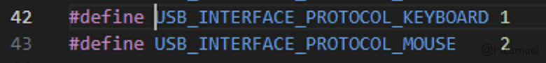
Figure 18: Macro definitions for bInterfaceProtocol values in Linux source code
2.1.4 Endpoint Descriptor
The structure definition for the endpoint descriptor is:linux/include/uapi/linux/usb/ch9.hThe structure is as follows:
/* USB_DT_ENDPOINT: Endpoint descriptor */
struct usb_endpoint_descriptor {
    __u8  bLength;
    __u8  bDescriptorType;

    __u8  bEndpointAddress;
    __u8  bmAttributes;
    __le16 wMaxPacketSize;
    __u8  bInterval;

    /* NOTE:  these two are _only_ in audio endpoints. */
    /* use USB_DT_ENDPOINT*_SIZE in bLength, not sizeof. */
    __u8  bRefresh;
    __u8  bSynchAddress;
} __attribute__ ((packed));InUSBPcapCheck the information captured from the endpoint descriptors, as shown in Figure 19:
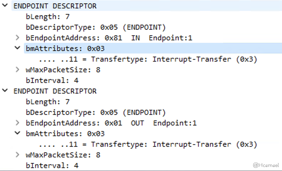
Figure 19: Viewing Endpoint Descriptors in Wireshark
The port number is defined in the endpoint descriptor, along with the direction of the port and the method of communication used for that port (in the diagram above, the communication method is defined as interrupt transfer), and the maximum size (8 bytes) of the communication data packet.
Next, I have outlined the file structure of the Linux Gadget directory, as shown below:
$ tree
.
├── bcdDevice
├── bcdUSB
├── bDeviceClass
├── bDeviceProtocol
├── bDeviceSubClass
├── bMaxPacketSize0
├── configs
│?? └── c.1
│??     ├── bmAttributes
│??     ├── hid.usb0 -> ../../../../usb_gadget/g1/functions/hid.usb0
│??     ├── MaxPower
│??     └── strings
│??         └── 0x409
│??             └── configuration
├── functions
│?? └── hid.usb0
│??     ├── dev
│??     ├── no_out_endpoint
│??     ├── protocol
│??     ├── report_desc
│??     ├── report_length
│??     └── subclass
├── idProduct
├── idVendor
├── max_speed
├── os_desc
│?? ├── b_vendor_code
│?? ├── qw_sign
│?? └── use
├── strings
│?? └── 0x409
│??     ├── manufacturer
│??     ├── product
│??     └── serialnumber
└── UDC
After research, it was found that the number of endpoints can be controlled through the no_out_endpoint file. By default, there are two endpoints, IN/OUT. If the value of the no_out_endpoint file is 1, the endpoint descriptor has only one IN endpoint. Another report_length file is used to control the maximum length of the transmitted data packet, which is the bMaxPacketSize field.
2.1.5 String Descriptor
The final one is a string descriptor, the definition of the structure is also located.ch9.hIt seems like your message might not have come through correctly. Could you please try sending the text again? I am here to help with translating any text you have.
struct usb_string_descriptor {
    __u8  bLength;
    __u8  bDescriptorType;

    __le16 wData[1];        /* UTF-16LE encoded */
} __attribute__ ((packed));
The role of a string descriptor is primarily to identify information, for example inUSB Tree ViewThe USB device information displayed is obtained through string descriptors.
You can inUSBTree ViewIn the view, examine all string descriptors, as shown in Figure 20:
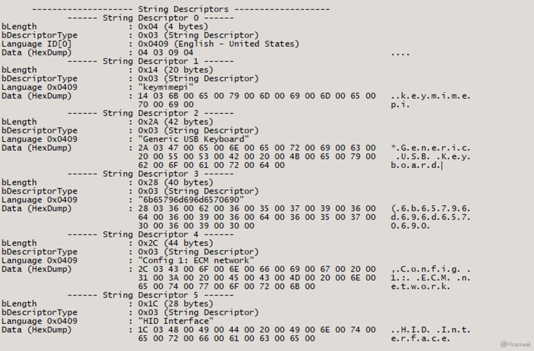
Figure 20: Viewing string descriptor in USB Tree View
In the interface descriptor,iInterfaceThe value of the field is the offset of the string descriptor.
2.1.6 HID Report Descriptor
When the USB host identifies a USB device as a USB HID device through the interface descriptor, it will then retrieve the HID report descriptor. The HID report descriptor captured in USBPcap is shown in Figure 21:
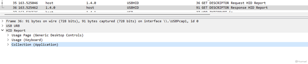
Figure 21: Viewing HID Report Descriptor with Wireshark
The code to define an HID report descriptor is located inbashIn the script it appears as follows:
# Write the report descriptor
# Source: https://www.kernel.org/doc/html/latest/usb/gadget_hid.html
echo -ne \\x05\\x01\\x09\\x06\\xa1\\x01\\x05\\x07\\x19\\xe0\\x29\\xe7\\x15\\x00\\x25\\x01\\x75\\x01\\x95\\x08\\x81\\x02\\x95\\x01\\x75\\x08\\x81\\x03\\x95\\x05\\x75\\x01\\x05\\x08\\x19\\x01\\x29\\x05\\x91\\x02\\x95\\x01\\x75\\x03\\x91\\x03\\x95\\x06\\x75\\x08\\x15\\x00\\x25\\x65\\x05\\x07\\x19\\x00\\x29\\x65\\x81\\x00\\xc0 > "${FUNCTIONS_DIR}/report_desc"
The HID report descriptor in the example is sourced from a Linux kernel example, as shown in Figure 22:
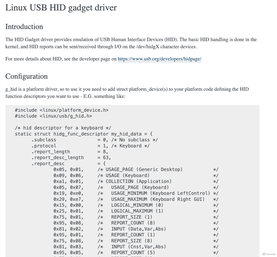
Figure 22: Linux USB HID Gadget Driver Documentation
So, the next step requires us to be able to successfully interpret HID report descriptors. You can refer to the official documentation; the advantage of the official documentation is that it is comprehensive. However, the downside is that the content is extensive, making it less suitable for beginners. The official documentation is more appropriate as a reference manual after you’ve gotten started.
2.1.6.1 Parsing HID Configuration Descriptor
Let’s take a look first.key-mime-piThe project’s communication code, detailing how the Raspberry Pi informs the host which buttons have been controlled, is as follows:
def send(hid_path, control_keys, hid_keycode):
    with open(hid_path, 'wb+') as hid_handle:   # hid_path = "/dev/hidg0"
        buf = [0] * 8
        buf[0] = control_keys
        buf[2] = hid_keycode
        hid_handle.write(bytearray(buf))
        hid_handle.write(bytearray([0] * 8))
Every key operation requires sending two 8-byte buffers to the USB host (the endpoint descriptor limits the maximum packet size to 8 bytes). All 8 bytes of the second buffer are set to 0. The first byte of the first buffer is a control character. Through research, it was found that 8 control characters are set as follows:
#define KEY_LEFTCTRL 0xe0 // Keyboard Left Control
#define KEY_LEFTSHIFT 0xe1 // Keyboard Left Shift
#define KEY_LEFTALT 0xe2 // Keyboard Left Alt
#define KEY_LEFTMETA 0xe3 // Keyboard Left GUI
#define KEY_RIGHTCTRL 0xe4 // Keyboard Right Control
#define KEY_RIGHTSHIFT 0xe5 // Keyboard Right Shift
#define KEY_RIGHTALT 0xe6 // Keyboard Right Alt
#define KEY_RIGHTMETA 0xe7 // Keyboard Right GUIGUIIt’s the Windows key on Windows, and the Command key on Mac.
The second byte of the first buffer is not set, defaulting to 0. The third byte to the eighth byte, spanning 6 bytes in length, corresponds to the key input.
After gaining a general understanding of how to send data to a USB host, let’s take a look at the HID report descriptor.
static struct hidg_func_descriptor my_hid_data = {
      .subclass               = 0, /* No subclass */
      .protocol               = 1, /* Keyboard */
      .report_length          = 8,
      .report_desc_length     = 63,
      .report_desc            = {
              0x05, 0x01,     /* USAGE_PAGE (Generic Desktop)           */
              0x09, 0x06,     /* USAGE (Keyboard)                       */
              0xa1, 0x01,     /* COLLECTION (Application)               */
              0x05, 0x07,     /*   USAGE_PAGE (Keyboard)                */
              0x19, 0xe0,     /*   USAGE_MINIMUM (Keyboard LeftControl) */
              0x29, 0xe7,     /*   USAGE_MAXIMUM (Keyboard Right GUI)   */
              0x15, 0x00,     /*   LOGICAL_MINIMUM (0)                  */
              0x25, 0x01,     /*   LOGICAL_MAXIMUM (1)                  */
              0x75, 0x01,     /*   REPORT_SIZE (1)                      */
              0x95, 0x08,     /*   REPORT_COUNT (8)                     */
              0x81, 0x02,     /*   INPUT (Data,Var,Abs)                 */
              0x95, 0x01,     /*   REPORT_COUNT (1)                     */
              0x75, 0x08,     /*   REPORT_SIZE (8)                      */
              0x81, 0x03,     /*   INPUT (Cnst,Var,Abs)                 */
              0x95, 0x05,     /*   REPORT_COUNT (5)                     */
              0x75, 0x01,     /*   REPORT_SIZE (1)                      */
              0x05, 0x08,     /*   USAGE_PAGE (LEDs)                    */
              0x19, 0x01,     /*   USAGE_MINIMUM (Num Lock)             */
              0x29, 0x05,     /*   USAGE_MAXIMUM (Kana)                 */
              0x91, 0x02,     /*   OUTPUT (Data,Var,Abs)                */
              0x95, 0x01,     /*   REPORT_COUNT (1)                     */
              0x75, 0x03,     /*   REPORT_SIZE (3)                      */
              0x91, 0x03,     /*   OUTPUT (Cnst,Var,Abs)                */
              0x95, 0x06,     /*   REPORT_COUNT (6)                     */
              0x75, 0x08,     /*   REPORT_SIZE (8)                      */
              0x15, 0x00,     /*   LOGICAL_MINIMUM (0)                  */
              0x25, 0x65,     /*   LOGICAL_MAXIMUM (101)                */
              0x05, 0x07,     /*   USAGE_PAGE (Keyboard)                */
              0x19, 0x00,     /*   USAGE_MINIMUM (Reserved)             */
              0x29, 0x65,     /*   USAGE_MAXIMUM (Keyboard Application) */
              0x81, 0x00,     /*   INPUT (Data,Ary,Abs)                 */
              0xc0            /* END_COLLECTION                         */
      }
};
First isUSAGE_PAGEandUSAGEThese two fields can refer to the documentation. Currently, we can only select those predefined applications, which will affect some driver feature recognition.
Primarily focus on the collection section content, with collections byCOLLECTIONLet’s begin. Please provide the text content of the WordPress post you would like me to translate, keeping the original HTML and formatting elements untouched.END_COLLECTIONEnd.
The content of the collection can be divided into four parts, with the first part shown below:
0x05, 0x07,     /*   USAGE_PAGE (Keyboard)                */
0x19, 0xe0,     /*   USAGE_MINIMUM (Keyboard LeftControl) */
0x29, 0xe7,     /*   USAGE_MAXIMUM (Keyboard Right GUI)   */
0x15, 0x00,     /*   LOGICAL_MINIMUM (0)                  */
0x25, 0x01,     /*   LOGICAL_MAXIMUM (1)                  */
0x75, 0x01,     /*   REPORT_SIZE (1)                      */
0x95, 0x08,     /*   REPORT_COUNT (8)                     */
0x81, 0x02,     /*   INPUT (Data,Var,Abs)                 */
The first part specifies the function keys on the keyboard, with the minimum value beingKeyboard LeftControl(0xe0), the maximum value isKeyboard Right GUI(0xe7). The logical minimum is 0, and the maximum is 1; 1 indicates pressed, while 0 indicates released. A single button uses 1 bit. There are 8 buttons, which collectively occupy 1 byte. For instance: 0b00000001 indicatesLeftControlA key has been pressed. From here, we can press all 8 control keys at once.
The second part is as follows:
0x95, 0x01,     /*   REPORT_COUNT (1)                     */
0x75, 0x08,     /*   REPORT_SIZE (8)                      */
0x81, 0x03,     /*   INPUT (Cnst,Var,Abs)                 */
There are 8 1-bit values, totaling 1 byte, and it is a constant (Cnst stands for constant throughout). In the context, there’s no evidence of a value being set, so it is assumed to be the default value 0. When transmitting data, even if 0 is not sent, it does not affect the process, as the driver does not actively recognize the data of this byte.
Section Three is as follows:
0x95, 0x05,     /*   REPORT_COUNT (5)                     */
0x75, 0x01,     /*   REPORT_SIZE (1)                      */
0x05, 0x08,     /*   USAGE_PAGE (LEDs)                    */
0x19, 0x01,     /*   USAGE_MINIMUM (Num Lock)             */
0x29, 0x05,     /*   USAGE_MAXIMUM (Kana)                 */
0x91, 0x02,     /*   OUTPUT (Data,Var,Abs)                */
0x95, 0x01,     /*   REPORT_COUNT (1)                     */
0x75, 0x03,     /*   REPORT_SIZE (3)                      */
0x91, 0x03,     /*   OUTPUT (Cnst,Var,Abs)                */
The above HID descriptor defines an LED function, occupying a total of 1 byte, with the highest 3 bits being constant 0, and the lower 5 bits representing the indicator lights on a keyboard. Common examples include: Num Lock indicator light, Caps Lock indicator light, Scroll Lock indicator light, etc. The host sends this to the device, and the on-off status of the keyboard lights is controlled by the USB host.
Part Four is as follows:
0x95, 0x06,     /*   REPORT_COUNT (6)                     */
0x75, 0x08,     /*   REPORT_SIZE (8)                      */
0x15, 0x00,     /*   LOGICAL_MINIMUM (0)                  */
0x25, 0x65,     /*   LOGICAL_MAXIMUM (101)                */
0x05, 0x07,     /*   USAGE_PAGE (Keyboard)                */
0x19, 0x00,     /*   USAGE_MINIMUM (Reserved)             */
0x29, 0x65,     /*   USAGE_MAXIMUM (Keyboard Application) */
0x81, 0x00,     /*   INPUT (Data,Ary,Abs)                 */
Defined the keyboard functions, with key values ranging from 0 to 0x65, consisting of a total of 102 keys. The logical values also span from 0 to 0x65. Each key occupies 1 byte, allowing for a maximum of 6 keys, which in total occupy 6 bytes.
With the HID report descriptor for the keyboard fully analyzed, we find that the descriptor’s definition corresponds with the format of our input data.
The first byte of the sent buffer represents 8 control keys, the second byte is fixed at 0, and the remaining 6 bytes are for input keys.
At this point, two issues have arisen:
1. The test-simulated keyboard is a 104-key keyboard. Why are there 102+8=110 values? After research, it was found as follows:
The comments provided in the code snippet appear to include some code definitions and explanations in both English and another language. Below, I've translated the non-English parts of the comments while maintaining the formatting and structure of the code:

```c
#define KEY_NONE 0x00 // No key pressed
#define KEY_ERR_OVF 0x01 // Keyboard Error Roll Over - used for all slots if too many keys are pressed ("Phantom key")
// 0x02 //  Keyboard POST Fail
// 0x03 //  Keyboard Error Undefined

#define KEY_102ND 0x64 // Keyboard Non-US \ and |
#define KEY_BACKSLASH 0x31 // Keyboard \ and |
// The two above conflict, there is one too many
#define KEY_HASHTILDE 0x32 // Keyboard Non-US # and ~
// It is likely that my keyboard does not have Non-US related keys
```

Let me know if you need further translation or assistance!
According to the calculations above, it happens to be a 104-key keyboard.
2. Why is it necessary to send a packet filled with 0s? Research has shown that the packet sent from the USB device to the USB host indicates the current status of the keyboard. A complete keystroke operation involves pressing a key and then releasing it. The packet sent informs the host which keys have been pressed, while the second packet filled with 0s informs the host that all keys have been released.
3 Future Research Directions
Reference Resources
The research in this article concludes here, and the content of the upcoming article will consider exploring the following directions:
- Fine-tune the HID report descriptor and observe its impact on practical usage.
- By modifying the interface descriptor fields and HID report descriptor fields, simulate a mouse.
- Researching the game controller, it’s worth mentioning that game controllers also use the HID protocol. However, I did not find relevant definitions in the Linux code.
- Research non-HID protocols, such as USB drives, network cards, and printers.
- Research-driven system details in the Linux kernel’s drivers directory can search for the `module_usb_driver` string, which is a macro-defined function. USB host-side drivers are registered with the kernel through this function.